GB.COMPACTAHSK.210520
Registered design. The company reserves the right to make design changes without prior notice.
www.swegon.com 13
7
USER LEVEL
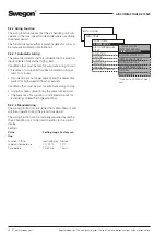
7.1 Temperature
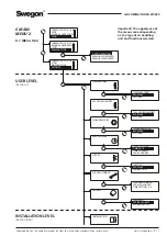
The basic functions can be preset at INSTALLATION LEV-
EL and the values can be read and set at USER LEVEL.
See also Section 9.2 in which the functions for
temperature are described in detail.
IMPORTANT!
If you intend to substantially alter the tempera-
ture settings, you should first stop the air handling unit before
doing so.
7.1.1 Readings
Used for checking the performance.
7.1.2 Settings
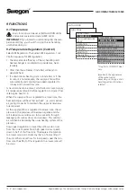
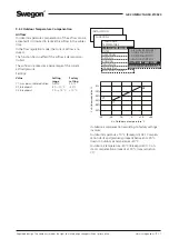
ERS REGULATION 1
The control unit regulates the relationship between the sup-
ply air and the extract air temperatures according to a factory
preset curve.
Settings
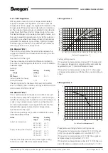
(see the chart to the right as well):
Value
Setting
Factory
range settings
Step
1 - 3
1
EA/SA Differential
1-5 °C*
2 °C
Breakpoint (refers to
15-23 °C*
20 °C
extract air temperature)
*) The setting range can be changed. See Section 14.3, Min./
Max. Setting.
ERS REGULATION 2
The control unit regulates the relationship between the supply
air and extract air temperatures according to a custom-plotted
curve. The curve has three adjustable breakpoints.
Settings
(see the chart to the right as well):
Value
Setting
Factory
range settings
Extract air temperature
X1
10-40 °C
15 °C
X2
10-40 °C
20 °C
X3
10-40 °C
22 °C
Supply air temperature
Y1
10-40 °C
20 °C
Y2
10-40 °C
18 °C
Y3
10-40 °C
14 °C
ERS Regulation 1
TEMPERATURE
*TEMPERATURE*
READINGS
SETTINGS
*TEMPERATURE*
READINGS
SETTINGS
ERS REGULATION 1
ERS REGULATION 2
Important! The
appearance of the menus
varies depending on the
type of air handling unit
and functions selected.
15 16 17 18 19 20 21 22 23 24 25 26 27 28 29 30 31 32
15
16
17
18
19
20
21
22
23
24
14
Supply air temperature setpoint
°
C
Extract air temperature °C
Step 3
Step 2
Step 1
1
2
3
15
20
22
9
10
12
15
20
25
27
X = Extract air temperature °C
Y =
Supply air temperature setpoint
°
C
ERS Regulation 2


