


3-38 ENGINE CONTROL SYSTEM
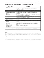
CIRCUIT VOLTAGE TABLE
TERMINAL
CIRCUIT
STANDARD
CONDITION / REMARKS
NUMBER
VOLTAGE
1
–
–
–
2
Emergency stop switch
Approx. 5V
Ignition switch ON, plate IN
Approx. 0V
Ignition switch ON, plate OUT
3
Buzzer cancel
Approx. 12V
Ignition switch ON, key pushed
Approx. 0V
Ignition switch ON, key not pushed
4
Tachometer
–
–
5
Neutral switch / Engine start signal
Approx. 0V
Ignition switch ON, shift into NEUTRAL
Approx. 2.5V Ignition swich ON, shift into FORWARD or REVERSE
6 – 12V
While engine cranking
6
–
–
–
7
Exhaust manifold temperature sensor
0.10 – 4.63V Ignition switch ON
8
–
–
–
9
Cylinder temperature sensor
0.10 – 4.63V Ignition switch ON
10
Ground for ECM
–
–
11
Ground for sensors
–
–
12
OIL lamp
–
–
13
Ground for ECM main relay
–
–
14
–
–
–
15
CMP sensor
–
–
16
PC communication
–
–
17
TEMP lamp
–
–
18
IAC valve solenoid (–)
Approx. 12V
Ignition switch ON
19
–
–
–
20
Ground for power source
–
–
21
–
–
–
22
No. 4 Fuel injector (–)
Approx. 12V
Ignition switch ON
23
Oil pressure switch
Approx. 5V
While engine running
Approx. 0V
Other than above (Ignition switch ON)
24
CTP switch
Approx. 5V
Ignition switch ON, throttle not fully closed
Approx. 0V
Ignition switch ON, throttle fully closed
25
REV-LIMIT lamp
–
–
26
CHECK ENGINE lamp
–
–
27
Buzzer
–
–
28
–
–
–
29
MAP sensor
0.20 – 4.53V Ignition switch ON
30
ECM power source
Approx. 12V
Ignition switch ON
31
IAT sensor
0.04 – 4.46V Ignition switch ON
32
Ground for ECM
–
–
33
CKP sensor
Approx. 0.3V or 5V Ignition switch ON
34
O
2
feedback / PC communication
–
–
35
Power source for MAP sensor
Approx. 5V
Ignition switch ON
36
PC communication
–
–
37
Fuel pump (–)
Approx. 0V
For 3 sec. after ignition switch ON
While engine running
Approx. 12V
Other than above (Ignition switch ON)
38
No. 3 Fuel injector (–)
Approx. 12V
Ignition switch ON
39
No. 2 Fuel injector (–)
Approx. 12V
Ignition switch ON
40
No. 1 Fuel injector (–)
Approx. 12V
Ignition switch ON
41
Resistor
–
–
42
Ground for power source
–
–
43
No. 2 & 3 Ignition (–)
Approx. 12V
Ignition switch ON
44
No. 1 & 4 Ignition (–)
Approx. 12V
Ignition switch ON
Содержание DF 60
Страница 1: ...9 9 5 0 0 9 9 E 1 0 0 1 E For 03 model ...
Страница 52: ...3 4 ENGINE CONTROL SYSTEM WIRING DIAGRAM FOR ENGINE CONTROL ENGINE CONTROL MODULE ...
Страница 55: ...ENGINE CONTROL SYSTEM 3 7 ECM INTERNAL STRUCTURE ...
Страница 282: ...Prepared by Marine Power Products Division 1st Ed September 2002 Manual No 99500 99E10 01E Printed in Japan 284 ...
Страница 283: ...TK Printed in Japan K3 ...


