ENGINE CONTROL SYSTEM 3-29
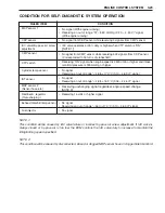
CONDITION FOR SELF-DIAGNOSTIC SYSTEM OPERATION
NOTE 1:
This condition will be caused by IAC valve failure or incorrect by-pass air screw adjustment. If IAC valve is
always closed or by-pass air is too low, the ECM controls the IAC valve duty to increase to maintain the
idling/trolling speed specified.
NOTE 2:
This condition will be caused by disconnected, kinked or clogged MAP sensor hose or clogged inlet maniford.
FAILED ITEM
CONDITION
MAP sensor 1
CKP sensor
CMP sensor
CTP switch
Cylinder temp. sensor
IAT sensor
MAP sensor 2
(Sensor hose etc.)
Rectifier & regulator
(Over-charging )
Exhaust manifold temp. sensor
IAC valve/By-pass air screw
adjustment
• No signal from CKP sensor while receiving 3 signals from CMP sensor
• No signal (With engine running)
• Receiving an out of range “37 – 860 mmHg (0.20 – 4.53 V)” signal
(With engine running)
• IAC valve operates at 90% duty or higher when CTP switch is “ON”
[
NOTE 1
]
• No signal from CMP sensor while receiving 544 signals from CKP sensor
(Corresponded to 16 turns of crankshaft)
• Receiving “ON” signal when engine speed is 2500 r/min or higher and intake
manifold pressure is 300 mmHg or higher
• No signal
• Receiving an out of range “– 46 to +170 °C (0.10 – 4.63 V)” signal
• No signal
• Receiving an out of range “– 46 to +169 °C (0.04 – 4.46 V)” signal
• Receiving unchanging signal regardless engine speed change
[
NOTE 2
]
• Receiving 16 volts or higher signal
• No signal
• Receiving an out of range “– 46 to +170 °C (0.10 – 4.63 V)” signal
Fuel injector
• No signal
Содержание DF 60
Страница 1: ...9 9 5 0 0 9 9 E 1 0 0 1 E For 03 model ...
Страница 52: ...3 4 ENGINE CONTROL SYSTEM WIRING DIAGRAM FOR ENGINE CONTROL ENGINE CONTROL MODULE ...
Страница 55: ...ENGINE CONTROL SYSTEM 3 7 ECM INTERNAL STRUCTURE ...
Страница 282: ...Prepared by Marine Power Products Division 1st Ed September 2002 Manual No 99500 99E10 01E Printed in Japan 284 ...
Страница 283: ...TK Printed in Japan K3 ...

