


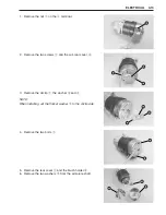
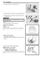


ELECTRICAL 4-7
TROUBLESHOOTING
NOTE:
Before troubleshooting the electric starter system, make sure the followings:
•
Battery is fully charged.
•
All cables / wires are securely connected.
•
Shift is in “NEUTRAL” position.
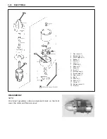
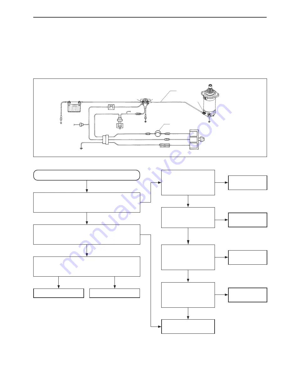
Circuit check schematic
Check starter motor.
(See page 4-14.)
Sub cable
1
+
-
3
Starter motor
GND
Ignition switch
Neutral switch
ST
BAT
GND
GND
Neutral
switch
30A Fuse
GND
GND
Battery
Starter motor relay
2
Starter motor will not run.
Check if there is “click” sound of relay when
turning ignition switch “START”.
Is there “click” sound?
Measure voltage at terminal
2
while turning
ignition switch at “START”.
It must be above 12 V. Is result OK?
Measure voltage at terminal
3
while turning
ignition switch “START”.
It must be above 12 V. Is result OK?
Starter motor failure
Sub cable failure
Measure voltage at
terminal
1
. It must
be above 12V.
Is result OK?
Check if 30A fuse is
in good condition.
Is result OK?
Check ignition switch
function.
(See page 4-8.)
Is result OK?
Check function of both
neutral switches. (See
page 4-8 and 4-9.)
Is result OK?
Check starter motor
relay.
(See page 4-9.)
Starter motor relay
failure
Battery cable
failure
30A fuse
failure
Ignition switch
failure
Neutral switch
failure
YES
YES
YES
NO
YES
YES
YES
NO
NO
NO
NO
NO
NO
Содержание DF 60
Страница 1: ...9 9 5 0 0 9 9 E 1 0 0 1 E For 03 model ...
Страница 52: ...3 4 ENGINE CONTROL SYSTEM WIRING DIAGRAM FOR ENGINE CONTROL ENGINE CONTROL MODULE ...
Страница 55: ...ENGINE CONTROL SYSTEM 3 7 ECM INTERNAL STRUCTURE ...
Страница 282: ...Prepared by Marine Power Products Division 1st Ed September 2002 Manual No 99500 99E10 01E Printed in Japan 284 ...
Страница 283: ...TK Printed in Japan K3 ...


