


ENGINE CONTROL SYSTEM 3-31
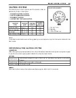
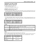
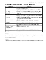
When the ignition switch is initially turned “ON” (from “OFF”),
the ECM tests the caution system by turning on all four lamps
in the monitor-tachometer and sounding the caution buzzer for
an initial two seconds.
For the next three seconds, the ECM indicates the total operat-
ing hours, using a combination of the tachometer needle and
“REV-LIMIT” lamp flashing.
NOTE:
The total operating hours displayed are those of actual engine
operation, not ignition switch “ON” time.
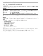
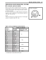
CHART OF TOTAL OPERATING HOURS INDICATION
Total
operating
hours
MONITOR-TACHOMETER
Needle
1
1
1
1
1
indication
REV-LIMIT lamp
2
2
2
2
2
flashing *
0 h – (49 h)
50 h
60 h
No
540 h
550 h
560 h
1 time
1040 h
1050 h
2 times
1540 h
1550 h
3 times
2030 h
2040 h or over
3 times
MONITOR-TACHOMETER
No
500 rpm
600 rpm
5400 rpm
500 rpm
600 rpm
5400 rpm
500 rpm
5400 rpm
500 rpm
5300 rpm
5400 rpm
* : One flashing is corresponded to 500 hours.
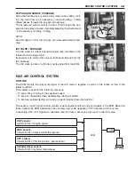
OPERATING HOUR INDICATION SYSTEM
(For remote control model)
Содержание DF 60
Страница 1: ...9 9 5 0 0 9 9 E 1 0 0 1 E For 03 model ...
Страница 52: ...3 4 ENGINE CONTROL SYSTEM WIRING DIAGRAM FOR ENGINE CONTROL ENGINE CONTROL MODULE ...
Страница 55: ...ENGINE CONTROL SYSTEM 3 7 ECM INTERNAL STRUCTURE ...
Страница 282: ...Prepared by Marine Power Products Division 1st Ed September 2002 Manual No 99500 99E10 01E Printed in Japan 284 ...
Страница 283: ...TK Printed in Japan K3 ...


