POWER UNIT 6-5
INSTALLATION
Installation is reverse order of removal with the special attention
to the following steps.
!
Do not re-use the gaskets once removed. Always use
new gaskets.
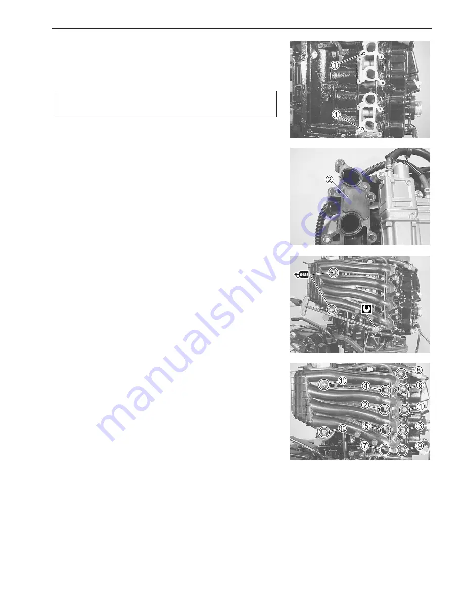
• Install the two dowel pins
1
and the gaskets
2
.
• Apply the thread lock to the two bolts as shown.
"
99000-32050: THREAD LOCK “1342”
• Tighten the eight bolts and the three nuts according to the
numerical order as shown.
#
Intake manifold bolt/nut: 25 N.m (2.5 kg-m, 18.0 lb-ft)
• Install the fuel injector and the delivery pipe.
CHECKING
Check hose routing. (See the page 10-8 to 10-12.)
Check wire routing. (See the page 10-2 to 10-7.)
Check for fuel leakage and water leakage.
Содержание DF 60
Страница 1: ...9 9 5 0 0 9 9 E 1 0 0 1 E For 03 model ...
Страница 52: ...3 4 ENGINE CONTROL SYSTEM WIRING DIAGRAM FOR ENGINE CONTROL ENGINE CONTROL MODULE ...
Страница 55: ...ENGINE CONTROL SYSTEM 3 7 ECM INTERNAL STRUCTURE ...
Страница 282: ...Prepared by Marine Power Products Division 1st Ed September 2002 Manual No 99500 99E10 01E Printed in Japan 284 ...
Страница 283: ...TK Printed in Japan K3 ...


