9
MOUNTING YOUR WINCH
Improper
mounting
can cause personal injury.
Improper mounting could
damage your winch and void
warranty.
MINIMUM ELECTRICAL
REQUIREMENTS
A 60 amp alternator and battery
with 440 cold-cranking amperes
capacity are the minimum recom-
mended power sources. If the winch
is in heavy use, an auxiliary battery
is recommended.
Under some circumstances, it may
be appropriate to install additional
circuit protection devices (circuit
breakers). If in doubt, seek
appropriate advice.
Superwinch recommends that all
winch electrical systems can be readi-
ly and quickly isolated from their
electrical supply in the event of an
emergency. The winch electrical sys-
tem should always be isolated when
the winch is not in use.
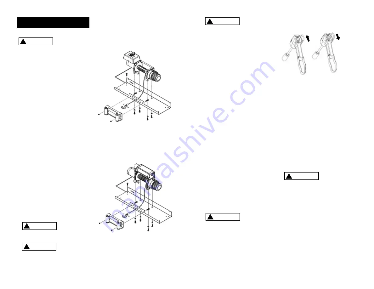
1. Install mounting kit or structural
support for winch.
2. Mount the winch to a mounting
kit base plate or to the mount
that you designed. Mounting
plate should be a minimum of
1/4” (6.3mm) thick. The ends of
the mounting bolts must not
contact the opposite side of
the casting.
Do not sub-
stitute any
strength grade weaker than
SAE Grade 8 (ISO 10.9).
When mount-
ing your EP
winch in a foot-forward position,
the solenoid pack MUST be
remote mounted. Also, when
remote mounting, the solenoid
pack may be mounted in any
configuration EXCEPT inverted
(i.e. solenoid studs facing down).
Inverted mounting may cause
erratic operation.
WARNING
!
WARNING
!
Automobile bat-
teries contain
gasses which are flammable and
explosive. Wear eye protection
during installation and remove all
metal jewelry. Do not lean over
battery while making connections.
3. Route the long red and black color
coded wires to the battery. To
ensure against insulation abrasion
and/or cutting, apply several layers
of electrical tape where wiring may
come in contact with sharp parts on
the vehicle. Attach the red color
coded wire to the battery positive
terminal, and reattach the terminal
to the battery.
If your vehicle is equipped with side
pole terminals, it may be necessary
to obtain auxiliary side terminal
bolts from your local auto parts
dealer to make these connections.
Connect the black color coded wire
to the battery negative terminal,
then connect the terminal to the
battery.
4. Turn the freespool clutch lever to
the “disengaged” position. Pull
several feet of wire rope off the
drum. Return the clutch lever
back to the “Engaged” position.
Plug in remote pendant control.
Push button momentarily to
check wire rope drum rotation
direction. If drum rotates in the
wrong direction, recheck your
wiring.
To prevent
unauthorized
use of the winch, remove pendant
control and store in a clean dry area
such as the glove box.
PENDANT OPERATION
The handheld pendant switch
activates a solenoid that activates
power to the winch motor.
To connect the pendant control,
remove the cover on the plug
receptacle and insert the plug end
of remote switch. The plug on the
pendant control cord is keyed and
will fit into the socket only one
way.
The switch trigger returns to the
“Off” position when released.
To change direction, move the
toggle in the other direction.
The switch
assembly
must be kept free of dirt and
moisture to ensure safe operation.
WARNING
!
I N S T A L L A T I O N
8
CAUTION
!
Figure 7
Figure 6
CAUTION
!
EP 6.0/9.0
EPi 6.0/9.0
Rope In
Rope Out
CAUTION
!
Содержание EP/EPi6.0
Страница 28: ...54 55 N O T E S N O T E S...


