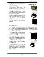


Chapter 2: Installation
2-19
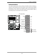
LAN1/LAN2
®
S
UPER X7DAL-E+
FP Control
Fan3
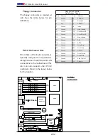
IDE
Floppy
Fan4
SATA3
SATA5
SMB
Slot1 PCI 33 MHz
JD1
Battery
CTRLR
Slot3 PCI-X 133 MHz
North Bridge
COM1
ATX PWR
8-Pin PWR
24-Pin
CPU2
South
Bridge
Fan1
SATA2
SATA4
SATA1
SATA0
Slot6 PCI-E x16
JPL2
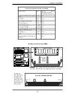
DIMM 1A (Bank 1)
DIMM 1B (Bank 1)
DIMM 2A (Bank 2)
DIMM 2B (Bank 2)
DIMM 3A (Bank 3)
DIMM 4A (Bank 4)
JBT1
KB/
Mouse
USB 0/1/2/3
5 0 0 0 X
BIOS
Fan5
Fan6
PWR
I
2
C
Slot5 PCI-33 MHz
Slot4 PCI-E x4 on x16 slot
JPAC1
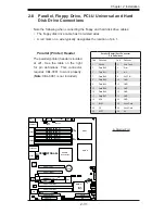
Printer
JPL1
JI
2
C1
JI
2
C2
JWOR
JWOL
Fan2
CPU1
LE2
LE3
LE1
LE5
LE4
USB4/5 USB6/7
Buzzer
ESB2
T-SGPIO1
T-SGPIO2
JL1
D31
Audio
4-Pin
PWR
FP Audio
JWD
CD-In
LAN
Slot2 PCI-X 133 MHz
S I/O
JPWF
Slot0 PCI-U
Audio
CTRL
Alarm
Reset
PWR
Force-On
COM2
2nd
Branch
1st
Branch
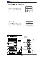
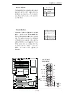
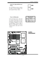
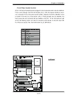
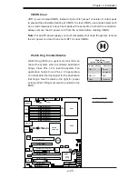
Power LED/Speaker
On the JD1 header, pins 1-3 are used
for a power LED and pins 4-7 are for
the speaker. See the table on the right
for speaker pin defi nitions. To use an
external speaker, connect a cable to
pins 4-7 of this header. To use the
onboard speaker, close pins 6-7 with
a jumper.
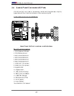
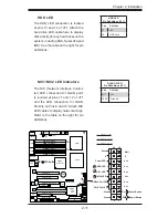
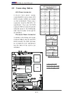
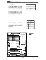
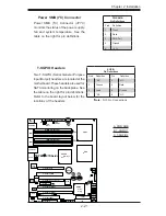
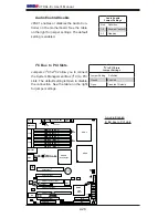
GLAN 1/2 (Giga-bit Ethernet
Ports)
Two G-bit Ethernet ports are located
at JLAN1 on the I/O backplane. This
port accepts RJ45 type cables.
Speaker Connector
Pin Defi nitions
Pin Setting Defi nition
Pins 6-7
Internal Speaker
Pins 4-7
External Speaker
A
B
A. GLAN1/2
B. PWR LED/Speaker
GLAN1
GLAN2
Содержание X7DAL-E+
Страница 1: ...X7DAL E USER S MANUAL Revision 1 1 ...
Страница 20: ...1 14 X7DAL E User s Manual Notes ...
Страница 54: ...2 34 X7DAL E User s Manual Notes ...
Страница 82: ...A 2 X7DAL E User s Manual Notes ...
Страница 88: ...C 4 X7DAL E User s Manual Notes ...


