background image

Chapter 5: Advanced Motherboard Setup

5-5

5-5  Installing the Processor and Heatsink


The PDSGE has a single LGA775 socket that supports Intel Pentium D or Pentium 4 

processors.  Intel's boxed Pentium 4 CPU package contains a CPU fan and heatsink 

assembly.  If you buy a CPU separately, make sure that you use a Intel-certifi ed 

multi-directional heatsink and fan only.   

!

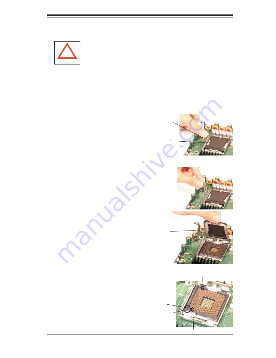
1. Press the socket lever to release the 

load plate that covers the CPU socket 

from its locking position.

CPU socket (with load plate) 

Socket Lever

2. Carefully lift the socket lever up to 

open the load plate.

Load Plate

3.  Locate Pin 1 on the CPU socket. (Pin 

1 is closest to the notched corner of the 

housing.)  Please note that a North key 

and a South key (notches) are located 

at opposite sides of the CPU housing.

Load Plate

Pin 1 

South Key

Step 1

Step 2a

North Key

Step 2b

Step 3

Notched 

corner 

Avoid placing direct pressure to the top of the processor 

package.  Always remove the power cord fi rst before adding, 

removing or changing any hardware components.

Содержание SuperWorkstation 5035G-T

Страница 1: ...SUPER SUPERWORKSTATION 5035G T USER S MANUAL Revision 1 0...

Страница 2: ...R INABILITY TO USE THIS PRODUCT OR DOCUMENTATION EVEN IF ADVISED OF THE POSSIBILITY OF SUCH DAMAGES IN PARTICULAR THE VENDOR SHALL NOT HAVE LIABILITY FOR ANY HARDWARE SOFTWARE OR DATA STORED OR USED W...

Страница 3: ...uction The rst chapter provides a checklist of the main components included with the system and describes the main features of the Super PDSGE motherboard and the SC733T 450 chassis Chapter 2 Server I...

Страница 4: ...when adding or removing processors or main memory and when recon guring the motherboard Chapter 6 Advanced Chassis Setup Refer to Chapter 6 for detailed information on the SC733T 450 workstation chas...

Страница 5: ...v Preface Notes...

Страница 6: ...g up the System 2 2 Checking the Motherboard Setup 2 2 Checking the Drive Bay Setup 2 4 Chapter 3 System Interface 3 1 Overview 3 1 3 2 Control Panel Buttons 3 1 Reset 3 1 Power 3 1 3 3 Control Panel...

Страница 7: ...ference 5 11 5 9 Connector De nitions 5 12 Power Supply Connectors 5 12 PW_ON Connector 5 12 Reset Connector 5 12 Overheat LED OH 5 13 NIC1 JLAN1 LED 5 13 IDE SATA LED 5 13 Power On LED 5 13 NMI Butto...

Страница 8: ...2 6 3 System Fans 6 5 Fan Failure 6 5 Replacing System Fans 6 5 6 4 Drive Bay Installation 6 7 Serial ATA Drives 6 7 Installing Components in the 5 25 Drive Bays 6 10 6 5 Power Supply 6 11 Replacing...

Страница 9: ...5G T www supermicro com and for regular updates on supported processor speeds In addition to the motherboard and chassis various hardware components may have been included with the 5035G T as listed b...

Страница 10: ...DDR memory providing bandwidth of up to 6 4 GB s using DDR 400 SDRAM The MCH supports the following front side bus memory bus con gurations 800 MHz FSB with a 400 333 memory interface a 533 MHz FSB w...

Страница 11: ...and are RAID 0 RAID 1 RAID 5 and RAID 10 supported Note The operating system you use must have RAID support to enable the hot swap capability and RAID function of the Serial ATA drives PCI Expansion S...

Страница 12: ...pset System Block Diagram Note This is a general block diagram Please see Chapter 5 for details GLENWOOD SLOTS LGA775_PROCESSOR ICH 7R USB PORT_0 7 FWH LPC I O MS KB FDD SER 1 SER 2 PRN PRI_IDE VRM 10...

Страница 13: ...Control Panel The SC733T 450 s control panel provides important system monitoring and control information LEDs indicate power on network activity hard disk drive activity and overheat conditions The...

Страница 14: ...1 6 SUPERWORKSTATION 5035G T User s Manual Figure 1 2 Rear I O Panel Keyboard Mouse COM1 COM2 Ports USB0 1 Ports USB3 4 5 6 Ports Parallel Port LineIn LineOut MIC LAN Port...

Страница 15: ...dress SuperMicro Computer B V Het Sterrenbeeld 28 5215 ML s Hertogenbosch The Netherlands Tel 31 0 73 6400390 Fax 31 0 73 6416525 Email sales supermicro nl General Information support supermicro nl Te...

Страница 16: ...1 8 SUPERWORKSTATION 5035G T User s Manual Notes...

Страница 17: ...e location for setting up and operating the SuperWorkstation 5035G T It should be situated in a clean dust free area that is well ventilated Avoid areas where heat electrical noise and electromagnetic...

Страница 18: ...n slide the cover out of the chassis 2 Check the CPU processor You may have one processor already installed into the system board The processor should have its own heatsink attached See Chapter 5 for...

Страница 19: ...Chapter 2 System Installation 2 3 Figure 2 1 Accessing the Inside of the 5035G T...

Страница 20: ...lready installed If you need to install or remove an SATA drive please refer to the appropriate section in Chapter 6 3 Check the air ow Cooling air is provided by a 9 cm internal cooling fan and a 12...

Страница 21: ...nel This chapter explains the meanings of all LED indicators and any appropriate response you may need to take 3 2 Control Panel Buttons There are two push button buttons located on the front of the c...

Страница 22: ...its This LED should normally be illuminated when the system is operating HDD Channel activity for all HDDs This light indicates SATA and if present CD ROM drive activity when ashing NIC Indicates netw...

Страница 23: ...r 5 This LED will remain ashing or on as long as the overheat condition exists 3 4 Serial ATA Drive Carrier LEDs On the front of each Serial ATA drive carrier is a green LED When illuminated it indica...

Страница 24: ...3 4 SUPERWORKSTATION 5035G T User s Manual Notes...

Страница 25: ...g power you should rst power down the system with the operating system rst and then unplug the power cords of all the power supply units in the system When working around exposed electrical circuits a...

Страница 26: ...pulled into a cooling fan Remove any jewelry or metal objects from your body which are excellent metal conductors that can create short circuits and harm you if they come into contact with printed ci...

Страница 27: ...l components and printed circuit boards PCBs in their antistatic bags until ready for use Touch a grounded metal object before removing the board from the antistatic bag Do not let components or PCBs...

Страница 28: ...e that the chassis cover is in place when the 5035G T is operating to assure proper cooling Out of warranty damage to the 5035G T system can occur if this practice is not strictly followed Figure 4 1...

Страница 29: ...to handle them very carefully see previous chapter To prevent the P8SC8 motherboard from bending keep one hand under the center of the board to support it when handling The following measures are gene...

Страница 30: ...an 3 Check compatibility of motherboard ports and I O shield The PDSGE requires a chassis big enough to support a 12 x 9 6 motherboard such as Supermicro s SC733T 450 Make sure that the I O ports on t...

Страница 31: ...the layout on page 5 9 for connector locations Front side USB port cables J12 SATA drive cable SATA 0 3 Control Panel cable JF1 Floppy cable Floppy Connecting Power Cables The PDSGE has a 24 pin prima...

Страница 32: ...O ports Figure 5 1 Control Panel Header Pins Mouse Green Parallel Port Burgundy LAN Port Keyboard Purple COM1 COM2 Ports Turquoise USB0 1 Ports Figure 5 2 I O Ports NMI x Key Vcc 5V Stby Vcc 3V Vcc 3...

Страница 33: ...ad plate that covers the CPU socket from its locking position CPU socket with load plate Socket Lever 2 Carefully lift the socket lever up to open the load plate Load Plate 3 Locate Pin 1 on the CPU s...

Страница 34: ...rs of the CPU to make sure that the CPU is properly installed 7 Use your thumb to gently press the lever down and lock it in the hook 8 If the CPU is properly installed into the socket the black plast...

Страница 35: ...the protective lm is not removed from the heatsink 5 Apply the proper amount of thermal grease on the CPU If your heatsink came with a thermal pad please ignore this step 6 If necessary rearrange the...

Страница 36: ...Bit Windows 2000 Advanced Server Windows Server 2003 Enterprise Edition 64 Bit Windows Server 2003 Standard x64 Edition Windows XP Professional x64 Edition Windows Server 2003 Enterprise x64 Edition 2...

Страница 37: ...using a screw to secure the top of the card shield to the backpanel of the chassis The PCI slot shields protect the motherboard and its components from EMI and aid in proper ventilation so make sure...

Страница 38: ...LAN Port Pentium Processor LGA775 PXH Slot 5 PCI 33 MHz Slot7 PCI E x1 AUX CD Slot 2 PCI X 133 MHz Slot 6 PCI E x16 LAN Control ler North Bridge BIOS JPWAKE KB MS FAN5 Buzzer Audio J5 J4 JPW2 COM2 JPU...

Страница 39: ...OM2 COM 1 2 Ports FAN 1 5 FAN1 CPU Fan FAN2 3 4 5 Chassis Fan Headers Floppy Floppy Disk Connector FP Aud Front Panel Audio Header IDE IDE Connector J4 PS 2 Keyboard Mouse J5 Audio Port Line In Line O...

Страница 40: ...the right for the pin de nitions of the ATX 24 pin power connector You must also connect the 8 pin JPW2 processor power con nector to your power supply Refer to the table below right for the JPW2 12V...

Страница 41: ...Pin De nition 7 Vcc 8 Ground NIC1 LED Pin De nitions JF1 Pin De nition 11 Vcc 12 Ground IDE SATA LED Pin De nitions JF1 Pin De nition 13 Vcc 14 HD Active NIC1 JLAN1 LED The LED connections for JLAN1...

Страница 42: ...Ports The ATX PS 2 keyboard and the PS 2 mouse are located on J4 The mouse port is above the keyboard port See the table on the right for pin de nitions NMI Button The non maskable interrupt button h...

Страница 43: ...ee the table on the right for pin de nitions Universal Serial Bus Pin De nitions USB USB0 USB6 Pin De nition USB7 Pin De nition 1 5V 1 5V 2 PO 2 PO 3 PO 3 PO 4 Ground 4 Ground 5 N A 5 Key Wake On LAN...

Страница 44: ...DTR 9 RI 5 Ground 10 NC Power LED Pin De nitions JLED Pin De nition 1 Anode 2 Key 3 Cathode CD Header Auxiliary Audio Header A 4 pin CD header CD and an Auxiliary header AUX are included on the mothe...

Страница 45: ...so clear any passwords Instead of pins this jumper consists of contact pads to prevent accidentally clearing the contents of CMOS To clear CMOS 1 First power down the system and unplug the power cord...

Страница 46: ...4 5 6 and JPUSB2 is for the USB7 8 headers Keyboard Wake Up The JPWAKE1 jumper is used to al low the system to be woken up by depressing a key on the keyboard from an S1 or S3 state in Windows OS See...

Страница 47: ...that has frozen See the table on the right for jumper settings Watch Dog must also be enabled in BIOS Note when Watch Dog is enabled the user must write their own application software to disable the W...

Страница 48: ...yellow right LED indicates activ ity while the left LED may be green orange or off to indicate the speed of the connection See the table on the right for the functions associated with the left activi...

Страница 49: ...e onboard IDE connector interface and the other connector s to your hard drive s Consult the documentation that came with your disk drive for details on actual jumper locations and settings for the ha...

Страница 50: ...e 11 Ground 12 Drive Select B 13 Ground 14 Drive Select B 15 Ground 16 Motor Enable 17 Ground 18 DIR 19 Ground 20 STEP 21 Ground 22 Write Data 23 Ground 24 Write Gate 25 Ground 26 Track 00 27 Ground 2...

Страница 51: ...4 Host Data 8 5 Host Data 6 6 Host Data 9 7 Host Data 5 8 Host Data 10 9 Host Data 4 10 Host Data 11 11 Host Data 3 12 Host Data 12 13 Host Data 2 14 Host Data 13 15 Host Data 1 16 Host Data 14 17 Ho...

Страница 52: ...5 24 SUPERWORKSTATION 5035G T User s Manual Notes...

Страница 53: ...owing measures are generally suf cient to protect your equipment from static discharge Precautions Use a grounded wrist strap designed to prevent static discharge Touch a grounded metal object before...

Страница 54: ...he appropriate comn nector on the front control panel PCB printed circuit board Pull all excess cabling over to the control panel side of the chassis The LEDs inform you of system status see Figure 6...

Страница 55: ...Front View 5 25 Drive Bays System Reset Main Power SATA Active LED System LEDs Front Side USB Floppy Drive Bay SATA Drive Con guration Drive IDs are marked on the front bezel From bottom to top they a...

Страница 56: ...6 4 SUPERWORKSTATION 5035G T Manual Figure 6 3 Chassis Rear View Power Supply Fan PCI Expansion Slots I O Backplane 12 cm Exhaust Fan Power Supply...

Страница 57: ...Figure 2 1 for accessing the inside of the chassis 2 Removing the fan duct assembly 9 cm fan After removing the side chassis cover release the clips that secure the fan duct to the chassis You can the...

Страница 58: ...6 6 SUPERWORKSTATION 5035G T Manual Figure 6 5 Removing the 12 cm Exhaust Fan Figure 6 4 Removing the Fan Duct Assembly 9 cm Fan...

Страница 59: ...Use extreme caution when working around the SATA backplane Do not touch the backplane with any metal objects and make sure no ribbon cables touch the backplane or obstruct the air ow holes in the SAT...

Страница 60: ...n and removal from the chassis These carriers also work to promote proper air ow for the system For this reason even carriers without SATA drives must remain in the server If you need to add a new SAT...

Страница 61: ...or the locations of backplane connectors the reverse side of the backplane has four channel connectors that the SATA drives plug into when inserted with a SATA drive carrier See Figure 6 2 for drive n...

Страница 62: ...CD ROM into the bay and secure it to the chassis with the drive carrier screws you rst removed Attach the power and data cables to the drive Replace the top left chassis cover before restoring power...

Страница 63: ...supply First unplug the power cord from the power supply Then remove the power supply connectors going to the motherboard and the SATA backplane Finally remove the screws that secure the unit to the m...

Страница 64: ...6 12 SUPERWORKSTATION 5035G T Manual Notes...

Страница 65: ...computer is turned off a back up battery provides power to the BIOS Flash chip enabling it to retain the system parameters Each time the computer is powered on the computer is then con gured with the...

Страница 66: ...rogram can be activated in one of two ways 1 By pressing Del immediately after turning the system on or 2 When the following message appears brie y at the bottom of the screen during the POST Power On...

Страница 67: ...5 in IDE Channel 0 Master Slave IDE Channel 1 Master Slave IDE Channel 2 Master Slave IDE Channel 3 Master Slave These settings allow the user to set the parameters of the IDE Channels 0 1 Master Sla...

Страница 68: ...lt On This item sets the condition that activates the function of Halt On The options are All Error No Error All But Keyboard All But Diskette and All But Disk Key Base Memory Extended Memory Total Me...

Страница 69: ...s the POST messages to be displayed ACPI Function Select Enabled to activate BIOS support for Advanced Con guration and Power Interface features The settings are Enabled or Disabled ACPI Suspend Type...

Страница 70: ...TA Mode This setting allows you to select the Serial ATA mode for the system The options are IDE RAID and APCI On Chip Serial ATA Select Disabled to disable the SATA Controller Select Auto to allow th...

Страница 71: ...BC Input Clock This setting allows you to con gure the KBC input clock The options are 6 MHz 8 MHz 12 MHz and 16 MHz Onboard FDC Controller This setting allows you to set the onboard oppy disk control...

Страница 72: ...t Con guration Data Enabling this setting resets the extended system con guration data when you exit setup Do this when you have installed a new add on and the system recon guration has caused such a...

Страница 73: ...aturereachesthepre setthreshold analarmwillbeactivatedandawarning message will be displayed on screen The options are Disabled 500 C 1220 F 550 C 1310 F 600 C 1400 F 650 C 1490 F 700 C 1580 F 750 C 16...

Страница 74: ...nabled Set to Enabled for Windows XP and Linux 2 4x operating systems Disable for operating systems that do not support Hyper Threading Auto Detect PCI CLK Select Enabled to allow the system to automa...

Страница 75: ...ection Allows you to Enable or Disable Console Redirection The options are Disabled and Enabled Agent Connect Via This setting allows you to select the device to be used for Console Redirection Agent...

Страница 76: ...er key When prompted type a password in the dialogue box to set or to change the supervisor password Set User Password When Set User Password is highlighted on the above screen press the Enter key Whe...

Страница 77: ...devices First Boot Device Second Boot Device Third Boot Device This item allows the user to set the rst boot up device The options are Removable Hard Disk CDROM Legacy LAN IBA GE Slot21 and Disabled T...

Страница 78: ...s you may have made Your system should then continue with the boot up procedure Load Fail Safe Defaults Highlight this item and hit Enter to load the default settings for all items in the BIOS Setup T...

Страница 79: ...e using the LE2 and LE3 debug LEDs The following are lists of such messages Beep Code Description 1 long repetitive beep Memory module errors 1 long beep 2 short beeps VGA errors LE2 State Green LE3 S...

Страница 80: ...A 2 SUPERWORKSTATION 5035G T User s Manual Notes...

Страница 81: ...address 1000 0 02h Reserved 03h Initial Superio_Early_Init switch 04h Reserved 05h 1 Blank out screen 2 Clear CMOS error ag 06h Reserved 07h 1 Clear 8042 interface 2 Initialize 8042 self test 08h 1 T...

Страница 82: ...rix notebook platform 20h Reserved 21h HPM initialization notebook platform 22h Reserved 23h 1 Check validity of RTC value e g a value of 5Ah is an invalid value for RTC minute 2 Load CMOS settings in...

Страница 83: ...O chips 34h Reserved 35h Reserved 36h Reserved 37h Reserved 38h Reserved 39h Reserved 3Ah Reserved 3Bh Reserved 3Ch Test 8254 3Dh Reserved 3Eh Test 8259 interrupt mask bits for channel 1 3Fh Reserved...

Страница 84: ...ocessors multi processor platform 56h Reserved 57h 1 Display PnP logo 2 Early ISA PnP initialization Assign CSN to every ISA PnP device 58h Reserved 59h Initialize the combined Trend Anti Virus code 5...

Страница 85: ...go is supported If errors occur report errors and wait for keys If no errors occur or F1 key is pressed to continue Clear EPA or customization logo 80h Reserved 81h Reserved 82h 1 Call chipset power m...

Страница 86: ...ization 4 Power management nal initialization 5 Clear screen and display memory table 6 Program K6 write allocation 7 Program P6 class write combining 95h 1 Program daylight saving 2 Update keyboard L...

Страница 87: ...upport Windows XP 2000 2003 Operating Systems Serial ATA SATA Serial ATA SATA is a physical storage interface that uses a single cable with a minimum of four wires to create a point to point connectio...

Страница 88: ...tive Mode 1 Press the Del key during system bootup to enter the BIOS Setup Utility Note If it is the rst time powering on the system we recommend you load the Optimized Default Settings If you have al...

Страница 89: ...ears after Power On Self Test b When you see the above screen press the Ctrl and the I keys simultane ously to have the main menu of the SATA RAID Utility appear Note All graphics and screen shots sho...

Страница 90: ...ve and press Space to select it A triangle appears to con rm the selection of the drive f Use the Up Arrow Down Arrow keys to selet the stripe size ranged from 4 KB to 128 KB for the RAID 0 array and...

Страница 91: ...t the previous menu c When RAID Level item is highlighted press the Up Arrow Down Arrow keys to select RAID 1 Mirror and hit Enter d When the Capacity item is highlighted enter your RAID volume capaci...

Страница 92: ...w Down Arrow keys to select the stripe size from 4 KB to 128 KB for your RAID 10 and hit Enter The default setting is 6 4KB Note For a server please use a lower stripe size and for a multimedia system...

Страница 93: ...on Page C 3 displays e Use the Up Arrow Down Arrow keys to highlight a drive and press Space to select it A triangle appears to con rm the selection of the drive f Use the Up Arrow Down Arrow keys to...

Страница 94: ...te RAID Volume and press Enter b Use the Up Arrow Down Arrow keys to select the RAID set you want to delete and press Del A Warning message displays c When asked Are you sure you want to delete this v...

Страница 95: ...D set drive A Warning message displays d Press Y to reset the drive or type N to go back to the main menu Exiting the Intel Matrix Storage Manager Utility a From the main menu select item4 Exit and pr...

Страница 96: ...Controller from the list indicated in the XP 2000 2003 Setup Screen and press the Enter key f Press the Enter key to continue the installation process If you need to specify any additional devices to...

Страница 97: ...re boot the system before moving on to the next item on the list You should install everything here except for the SUPER Doctor utility and the LAN SCSI driver diskettes which are optional The bottom...

Страница 98: ...C 12 SUPERWORKSTATION 5035G T User s Manual b When the above screen appears click on the icon marked Next on the screen and the following screen will appear...

Страница 99: ...own in the following screen and click on the icon marked Next d Specify the folder that you want the program to be installed in and then click on the icon marked Next to begin the installation process...

Страница 100: ...ition Installation g Once the Application Accelerator RAID Edition installation is completed the fol lowing screen will appear and the system will start to re boot Note Once the XP 2000 2003 Operating...

Страница 101: ...to Page C 14 Driver Tool Installation Display Screen Click the icons showing a hand writing on paper to view the readme les for each item Click the computer icons to the right of these items to instal...

Страница 102: ...gement is called SD III Client The Supero Doctor III program included on the CDROM that came with your motherboard allows you to monitor the environment and operations of your system Supero Doctor III...

Страница 103: ...ed from our Website at ftp ftp supermicro com utility Supero_Doctor_III You can also download SDIII User s Guide at http www supermicro com PRODUCT Manuals SDIII UserGuide pdf For Linux we will still...

Страница 104: ...C 18 SUPERWORKSTATION 5035G T User s Manual Notes...

Страница 105: ...ash ROM Memory Capacity Four 240 pin DIMM sockets supporting up to 8 GB of unbuffered ECC DDR2 666 533 400 SDRAM single or dual channel Note Dual channel memory requires memory to be installed two mod...

Страница 106: ...cm exhaust fan One 1 9 cm cooling fan System Input Requirements AC Input Voltage 100 240V AC auto range Rated Input Current 100 10A 240V 5A Rated Input Frequency 50 to 60 Hz Power Supply Rated Output...

Страница 107: ...B EN 55022 Class B EN 61000 3 2 3 3 CISPR 22 Class B Electromagnetic Immunity EN 55024 CISPR 24 EN 61000 4 2 EN 61000 4 3 EN 61000 4 4 EN 61000 4 5 EN 61000 4 6 EN 61000 4 8 EN 61000 4 11 Safety EN 60...

Страница 108: ...D 4 SUPERWORKSTATION 5035G T User s Manual Notes...

Отзывы: