Chapter 6: Advanced Chassis Setup
6-3
6-2
S
UPER
S
ERVER 6018R-TD Manual
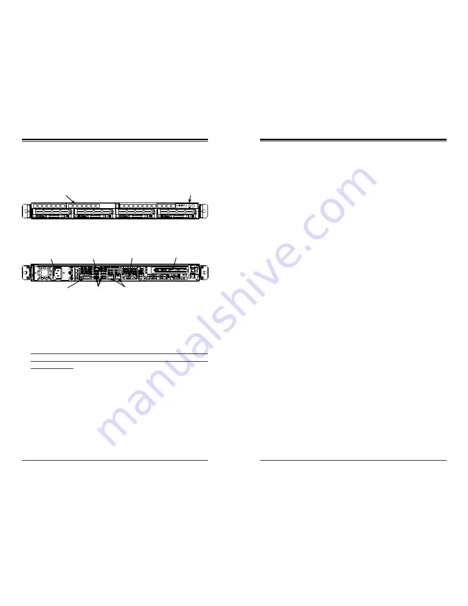
Figure 6-1. Chassis: Front and Rear Views
6-2 Control Panel
The control panel (located on the front of the chassis) must be connected to the JF1
connector on the serverboard to provide you with system status indications. These
wires have been bundled together as a ribbon cable to simplify the connection.
Connect the cable from JF1 on the serverboard to the appropriate header on the
Control Panel PCB (printed circuit board). Make sure the red wire plugs into pin 1
on both connectors.
Pull all excess cabling out of the airflow path.
The control panel LEDs inform you of system status. See "Chapter 3: System In-
terface" for details on the LEDs and the control panel buttons. Details on JF1 can
be found in "Chapter 5: Advanced Serverboard Setup."
Control Panel
Slim DVD-ROM Drive (optional)
6-3 System Fans
Two 10-cm blower fans and one 4-cm fan provide all the cooling needed for the
SuperServer 6018R-TD. It is very important that the chassis top cover is properly
installed and making a good seal in order for the cooling air to circulate properly
through the chassis and cool the components. See Figure 6-2.
System Fan Failure
Fan speed is controlled by system temperature via IPMI. If a fan fails, the remain-
ing fan will ramp up to full speed and the Information LED on the control panel will
turn on. Replace any failed fan at your earliest convenience with the same type
and model.
Accessing the Inside of the System
Remove the top chassis cover while the system is still running to determine which
of the two fans has failed:
1. Grasp the two handles on either side and pull the unit straight out until it
locks (you will hear a "click").
2. Depress the two buttons on the top of the chassis to release the top cover.
Push the cover away from you until it stops.
3. Lift the top cover from the chassis to gain full access to the inside of the
server. See Figure 6-2.
4. Power down the system before replacing a fan. Removing the power cord
from the power supply is also recommended as a safety precaution.
Replacing System Cooling Fans
1. Detach the fan wires from the serverboard then lift the failed 10-cm blower
or 4-cm fan off its mounting posts and completely free from the serverboard.
See Figure 6-3.
2. Replace the failed fan with an identical 10-cm blower or 4-cm fan (available
from Supermicro). Install the new fan in its proper place in the chassis by
positioning it on the two mounting posts.
3. Attach the fan wires to the same chassis fan header you removed them from.
4. Power up the system and check that the fan is working properly and that
the LED on the control panel has turned off. Finish by replacing the chassis
cover.
Power Supply Module
PCI Expansion Slot
COM Port
Dedicated IPMI LAN
USB Ports
LAN Ports
VGA Port
Содержание SUPERSERVER 6018R-TD
Страница 1: ...SUPERSERVER 6018R TD USER S MANUAL 1 0a...
Страница 9: ...1 6 SUPERSERVER 6018R TD User s Manual Notes...
Страница 15: ...2 10 SUPERSERVER 6018R TD User s Manual Notes...
Страница 18: ...3 4 SUPERSERVER 6018R TD User s Manual Notes...
Страница 43: ...5 26 SUPERSERVER 6018R TD User s Manual Notes...
Страница 49: ...6 10 SUPERSERVER 6018R TD Manual Figure 6 7 Removing Replacing the Power Supply...
Страница 72: ...7 44 SUPERSERVER 6018R TD User s Manual Notes...
Страница 74: ...A 2 SUPERSERVER 6018R TD User s Manual Notes...
Страница 77: ...B 4 SUPERSERVER 6018R TD User s Manual Notes...


