


27
19-38 DRUM SANDER OWNER’S MANUAL
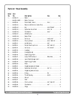
Technical Specifications
Index Part
No . No .
Description
Size
Qty .
62 ........ 480BS-162 ................... Base ........................................................................................................... 1
63 ........ 480BS-163 ................... Adjusting Lever (FAST) ............................................................................ 1
64 ........ 480BS-164 .................. Adjusting Rod .......................................................................................... 1
65 ........ 480BS-165 ................... Height Adjusting Plate .......................................................................... 1
66 ........ 480BS-166 .................. Round Socket Head Cap Screw ...................5/16”-18x1/2” ................ 4
67 ........ 480BS-167 ................... Lock Washer ....................................................5/16” .............................. 5
68 ........ 480BS-168 .................. Spring ........................................................................................................ 3
69 ........ 480BS-169 .................. Nylon Insert Lock Nut ...................................1/4”-20 ........................... 1
70 ........ 480DS-170 .................. Socket Head Cap Screw ................................M8x1.25x40 .................. 1
71 ......... 480DS-171 ................... Hex Nut w/ Washer .......................................5/16”-18 ......................... 4
72 ........ 480DS-172 ................... Block, Measuring Device ....................................................................... 1
73 ......... 480DS-173 ................... Hex Nut ............................................................M12x1.75 ........................ 1
74 ........ 480DS-174 ................... Stop Bolt ................................................................................................... 1
75 ......... 480DS-175 ................... Screw ................................................................M3x0.5x6 ...................... 2
76 ........ 480DS-176 ................... Lower Fixed Plate, DRO ......................................................................... 1
77 ......... 480BS-177 ................... Hex Cap Screw ................................................3/8”-16x3/4” ................. 4
78 ........ 480DS-178 .................. Hex Nut ............................................................M4x0.7 .......................... 1
79 ........ 480BS-179 ................... Tension Roller Bracket, Outer Right .................................................... 1
80 ........ 480BS-180 .................. Tension Roller Bracket, Outer Left ...................................................... 1
81 ......... 480BS-181 ................... E-Ring ................................................................E5 ................................... 1
82 ........ 480DS-182 .................. Upper Fixed Plate, DRO ......................................................................... 1
83 ........ 480DS-183 .................. Battery Cover .......................................................................................... 1
84 ........ 480DS-184 .................. Label .......................................................................................................... 1
85 ........ 480BS-185 ................... Height Direction Label ........................................................................... 1
86 ........ 480BS-186 .................. Maintenance Label ................................................................................. 1
87 ........ 480BS-187 ................... Warning Label .......................................................................................... 1
88 ........ 480DS-188 .................. Battery ...................................................................................................... 1
89 ........ 480DS-189 .................. Digital Readout Assembly (optional) ................................................. 1
90 ........ 635DS-280 .................. Fastener Tool (optional) ........................................................................ 1
Parts List—Head Assembly (continued)
Содержание 19-38
Страница 1: ...Owner s Manual 19 38 Drum Sander ...
Страница 23: ...23 Wiring Diagram TO GEAR MOTOR CONVEYOR TECHNICAL SPECIFICATIONS Wiring Diagram ...
Страница 24: ...24 19 38 DRUM SANDER OWNER S MANUAL Technical Specifications Head Assembly ...
Страница 28: ...28 19 38 DRUM SANDER OWNER S MANUAL Technical Specifications Conveyor and Motor Diagram ...
Страница 32: ...32 NOTES ...