


14
19-38 DRUM SANDER OWNER’S MANUAL
Abrasives
3. Insert the tapered end through the slot in the
right (inboard) end of the drum. Pull up on the
clip lever to open the clip, and pull the take-up
lever to the top.
4. After inserting the wrap end, release the clip
lever.
The take-up fastener is designed to automatically
take up any slack caused by stretching of the abra-
sive wrap. The abrasive wrap may stretch enough
in use to allow the take-up lever to reach its lowest
position so it no longer is able to maintain tension
on the wrap. If this occurs, it will be necessary to
reset the take-up lever by raising it, pushing the
wrap end into the slot, and then releasing the clip
lever.
Proper Abrasive Wrap Position
Position the abrasive wrap in the slot with suffi-
cient room between the inside of the slot and the
tapered end of the wrap to allow it to be pulled
into the drum as needed. If enough space is not left
between the wrap and the inside of the slot the
take-up fastener will not operate properly.
Abrasive Wrap Tension Adjustment
The abrasive wrap may stretch enough in use to al-
low the take-up lever to reach its lowest position.
If this occurs then tension is not longer maintained
on the abrasive wrap. To fix this reset the take-up
lever by raising it, pushing the abrasive wrap into
the slot and then releasing the clip lever.
Maximizing Abrasive Longevity
A sandpaper cleaning stick may be used to remove
deposits and help extend the life of the abrasive.
1. To use the cleaning stick, operate the sanding
drum with the dust cover open and dust collec-
tion on.
2. Hold the cleaning stick against the rotating
drum and move it along the drum surface.
3. Use a shop brush to remove any cleaning stick
remnants from the drums before resuming
sanding operations.
SAFETY NOTE: For your own safety
always wear eye protection while per-
forming abrasive cleaning and take all
precautions to avoid any contact with
hands or clothing on the uncovered
Содержание 19-38
Страница 1: ...Owner s Manual 19 38 Drum Sander ...
Страница 23: ...23 Wiring Diagram TO GEAR MOTOR CONVEYOR TECHNICAL SPECIFICATIONS Wiring Diagram ...
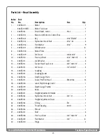
Страница 24: ...24 19 38 DRUM SANDER OWNER S MANUAL Technical Specifications Head Assembly ...
Страница 28: ...28 19 38 DRUM SANDER OWNER S MANUAL Technical Specifications Conveyor and Motor Diagram ...
Страница 32: ...32 NOTES ...