


25
19-38 DRUM SANDER OWNER’S MANUAL
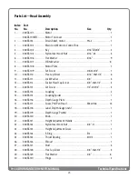
Technical Specifications
Index Part
No . No .
Description
Size
Qty .
1 ........... 480DS-101 ................... Motor ........................................................................................................ 1
.............. 480DS-101MFC ........... Motor Fan Cover ..................................................................................... 1
2 .......... 480BS-134 ................... Strain Relief, motor .......................................7N-2 ............................... 1
3 .......... 480DS-103 .................. Main Cord, Motor to Control Box ......................................................... 1
4 .......... 480BS-104 .................. Key ....................................................................3/16”SQx3/4” ................ 2
5 .......... 480BS-105 .................. Nylon Insert Lock Nut ...................................5/16”-24 ........................ 4
6 .......... 480BS-106 .................. Flat Washer .....................................................5/16” ............................. 9
7 ........... 480BS-107 ................... Oilite Washer .......................................................................................... 8
8 .......... 480BS-108 .................. Motor Plate .............................................................................................. 1
9 .......... 480BS-109 .................. Set Screw .........................................................#8-32x1/4” .................... 1
10 ........ 480BS-110 ................... Hex Cap Screw ................................................5/16”-18x1-1/4” ............ 6
11 ......... 480BS-111 .................... Lock Washer ....................................................3/8” ................................ 4
12 ......... 480BS-112 ................... Socket Head Cap Screw ................................3/8”-16x1-1/2” .............. 4
13 ......... 480BS-113 ................... Set Screw .........................................................1/4”-20x1/4” .................. 5
14 ......... 480BS-114 ................... Coupling .................................................................................................... 2
15 ......... 480BS-115 ................... Coupling Spider ....................................................................................... 1
16 ......... 480BS-116 ................... Depth Gauge Plate ................................................................................. 1
17 ......... 480BS-117 .................... Screw, Phil Pan Head .....................................M4x0.7x6 .................... 14
18 ......... 480BS-118 ................... Label, Depth Gauge (inch) ..................................................................... 1
19 ......... 480BS-119 ................... Depth Gauge Pointer ............................................................................. 1
20 ........ 480BS-120 .................. Knob .......................................................................................................... 1
21 ......... 480BS-121 ................... Height Adjustment Handle .................................................................. 1
22 ........ 480BS-122 ................... Nylon Insert Lock Nut ...................................5/8”-11 ........................... 1
23 ........ 480BS-123 ................... Height Adjustment Screw ..................................................................... 1
24 ........ 480BS-124 ................... E-Ring ................................................................E12 .................................. 1
25 ........ 480BS-125 ................... Thrust Bearing ................................................51103 .............................. 1
26 ........ 480BS-126 ................... Shroud ....................................................................................................... 1
27 ......... 480BS-127 ................... Stud ........................................................................................................... 4
28 ........ 480BS-128 .................. Hex Cap Screw ................................................3/8”-16x1-1/4” .............. 4
29 ........ 480BS-129 ................... Flat Washer .....................................................3/8” ............................... 8
30 ........ 480BS-130 .................. Hinge ......................................................................................................... 2
Parts List—Head Assembly
Содержание 19-38
Страница 1: ...Owner s Manual 19 38 Drum Sander ...
Страница 23: ...23 Wiring Diagram TO GEAR MOTOR CONVEYOR TECHNICAL SPECIFICATIONS Wiring Diagram ...
Страница 24: ...24 19 38 DRUM SANDER OWNER S MANUAL Technical Specifications Head Assembly ...
Страница 28: ...28 19 38 DRUM SANDER OWNER S MANUAL Technical Specifications Conveyor and Motor Diagram ...
Страница 32: ...32 NOTES ...