EN
EN
96
97
Protections, Troubleshooting & Maintenance
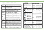
Protections
PV Over
Current/Power
When the charging current or power of the PV array exceeds the controller’s
rated current or power, it will change at the rated current or power.
PV Short Circuit
When not in the PV charging state, the controller will not be damaged in case
of a short-circuiting in PV array.
PV Short Circuit
When the polarity of the PV array is reversed, the controller may not be da-
maged and can continue to operate normally after the polarity is corrected.
Night Reverse
Charging
Prevents the battery from discharging to the PV module at night.
BATT1 and BATT2
Reverse Polarity
Fully protected against battery reverse polarity; no damage will occur to the
battery. Correct the miswire to resume normal operation.
BATT1
Over Voltage
When the battery voltage reaches the over voltage disconnect voltage, it will
automatically stop battery charging to prevent battery damagecaused by
over-charging.
BATT1
Over Discharge
When the battery voltage reaches the low voltage disconnect voltage, it will
automatically stop battery discharging to prevent battery damage caused by
over-discharging. (Any controller connected loads will be disconnected. Loads
directly connected to the battery will not be affected and may continue to
discharge the battery.)
BATT1
Overheating
The controller can detect the battery temperature through an external tempe-
rature sensor.The controller stops working when its temperature exceeds 65
°C and restart to work when its temperature is below 55 °C.
BATT1
Low Temperature
(Lithium Battery)
When the temperature detected by the optional temperature sensor is lower
than the Low Temperature Protection Threshold(LTPT), the controller will stop
charging and discharging automatically. When the detected temperature is
higher than the LTPT, the controller will be working automatically (The LTPT is
0 °C by default and can be set within the range of 10 ~ -40 °C).
Controller
Overheating
The controller is able to detect the temperature inside the controller. The
controller stops working when its temperature exceeds 85 °C and restart to
work when its temperature is below 75 °C.
TVSHigh Voltage
Transients
The internal circuitry of the controller is designed with Transient Voltage
Suppressors (TVS) which can only protect against high-voltage surge pulses
with less energy. If the controller is to be used in an area with frequent light-
ning strikes, it is recommended to install an external surge arrester.
Troubleshooting
Faults phenomenon
Possible reasons Troubleshooting
Charging LED indicator off during
daytime when sunshine falls on PV
modules properly
PVarray
disconnection
Confirm that PV wire conne-
ctions are correct and tight.
Wire connection is correct,the controller
is not working.
Battery voltage
is lower than
8.5V
Please check the voltage of
battery. At least 8.5V voltage
to activate the controller.
DDS Red fast flashing
Battery level shows full,
battery frame blink, fault
icon blink
BATT1
over voltage
Check if battery voltage is
higher than OVD(over voltage
disconnect voltage), and
disconnect the PV.
DDB red on solid
BATT1
over discharged
When the battery voltage is
restored to or above LVR(low
voltage reconnect voltage),
the load will recover
Battery level shows
empty, battery frame
blink, fault icon blink
Red fast flashing
BATT1
Overheating
The controller will automa-
tically turn the system off.
When the temperature de-
clines to be below 55 0C, the
controller will resume.
Battery level shows
current capacity, battery
frame blink, fault icon
blink, the temperature
icon blink, the tempe-
rature value blink, the
temperature unit blink.
Red fast flashing and
Green fast flashing
BATT1
System
voltage error
①
Check whether the battery
voltage match with the con-
troller working voltage.
②
Please change to a suitable
battery or reset the working
voltage.
①
System alarm system voltage error
when using Lead-acid battery
②
System
alarm an over discharge fault when the
③
BATT1 is 12V but set as 24V
④
System alarm an over-voltage fault
when BATT1 is 24V but set as 12V
Incorrect wiring
steps should not
connect BATT1
first and then
BATT2
①
Disconnect the system,
and reconnect the BATT2 first,
then reconnect BATT1.
②
BATT1 voltage level should
be the same as BATT2


