background image

www.sunrotor.com


Page 26 


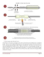
of  the  numbered  terminals,  and  power  up  the  controller  to  test  the  pump  direction.    If  no  water  is 
pumped, or if there is suction on the outlet pipe (this only applies to helical rotor pumps—centrifugal 
pumps will produce about ¼

th

 flow rate), turn off the power and switch any two of the three pump 

cable wires.  This will reverse the pump rotation.  Turn the pump back on, and confirm water flows 
at the proper rate from the pipe.  If no water flows after switching two wires, turn the power off and 
contact either your Authorized SunRotor

®

 Dealer or the SunRotor

® 

Technical Services Team at 1(866) 

246-7652. 

9.3


W

IRING 

P

OWER TO THE 

C

ONTROLLER


The SunRotor

®

 controller comes equipped with MC-4 cable connectors already attached to the proper 

controller  terminals.    Ensure  the  solar  array  wiring  configuration  and  voltage  before  attaching  the 
connectors  (See


Figure  5-3  Solar  Panel  Wiring  Diagram

).    Make  sure  the  controller  is  set  to  the 

OFF


position and plug the corresponding female and male ends together.  

9.4


P

OST

-I

NSTALLATION 

T

ESTING


The following tests are recommended after completing the installation. 

To  test the  low  water sensor,  disconnect  one  wire  to open  the  circuit.    Since  it  is  a  normally  closed 
switch, removing one  end of  the sensor cable or jumper  will trigger the circuit  logic to turn off the 
pump.  To test the timer function, set the timer to a low setting: somewhere between 0 and 5 (around 
2  ½  minutes).    Disconnect  the  cable  and  wait  for  the  pump  to  turn  off.    After  the  pump  stops, 
reconnect the cable.  The pump should automatically turn back on after the specified time has passed. 

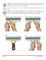
Most  tank  full  float  switches  are  normally  open.    To  test  it,  jumper  between  the  two  tank  full 
terminals.    This  will  create  a  closed  circuit,  and  the  pump  should  turn  off.    Once  the  jumper  is 
removed, the pump will restart. 

If  these  tests  do  not  produce  the  same  results,  see 

Section  10  Troubleshooting

.   

  Please  contact  your 

Authorized SunRotor

®

 Dealer or the SunRotor

®

 Technical Service Team directly at 1(866) 246-7652 if 

any further information is needed. 

10


T

ROUBLESHOOTING


10.1


I

F THE 

P

UMP 

D

OESN

R

UN


Most problems are caused by incorrect connections (in a new installation) or bad splices on the pump 
cable  or  low  water  sensor.    The 

SYSTEM

  light  will  indicate  that  the  system  is  switched  on.    It 

indicates that 

VOLTAGE

 is present, but there may not be sufficient power to start the pump. 

System appears dead, no lights showing on the controller: 

1.


Is there a disconnect switch or circuit breaker installed on the solar array circuit? Is it off? 

2.


Look for disconnected or damaged wires. 

3.


Is there any dust or debris on your solar array?  

Содержание Solar Pump

Страница 1: ...SunRotor Solar Pump Installation and Resource Manual...

Страница 2: ...ing Pole Guide for Top Of Pole Mounts 9 5 6 Seasonal Tilt of the Solar Array 10 5 7 Solar Array Wiring 10 5 8 Grounding and Lightning Protection 12 6 Pump Controller Installation 15 6 1 Pump Controlle...

Страница 3: ...gs 24 9 2 Wiring the Controller 24 9 3 Wiring Power to the Controller 26 9 4 Post Installation Testing 26 10 Troubleshooting 26 10 1 If the Pump Doesn t Run 26 10 2 Inspect the System 27 10 3 Electric...

Страница 4: ...LLC All Rights Reserved REGISTRATION FORMS Please look through the following form and fill out before during and after as needed This form is necessary to REGISTER YOUR WARRANTY The information provi...

Страница 5: ...Pump Serial Number Controller Model Controller Serial Number System Power PV Direct Battery System If PV Number of Panels Solar Panel Brand Solar Panel Wattage Watts Operating Voltage V Well Depth ft...

Страница 6: ...pump Protect the pump from sunlight or other heat sources SunRotor solar pumps are CLEAN WATER PUMPS Extreme sand or silt may cause the pump to stop or fill the pipe with debris Running it under these...

Страница 7: ...Module Mounting Rack 3 Water Pipe 4 Well Seal Assembly 5 Low Water Sensor 6 Submersible Pump 7 Conduit and Wiring from Controller to Well Seal 8 Wiring Harness from Controller to Solar Modules 9 DC I...

Страница 8: ...al weather resistant connection box with cooling fins cast on the back It has a clear cover which allows visible inspection of all of the connections and LED status lights It offers a wide operational...

Страница 9: ...ill reduce the power substantially slowing or possibly stopping the pump 5 3 SOLAR ORIENTATION For optimal performance the solar array must be oriented within 10 of true solar south Depending on locat...

Страница 10: ...local soil conditions is consulted FIGURE 5 1 MOUNTING POLE GUIDE Module Area Pole Size Steel Pipe Depth in Ground Height Above Ground Hole Diameter 15 SQ FT 2 SCH40 2 3 8 OD 30 36 48 72 8 12 20 SQ FT...

Страница 11: ...WIRING WARNING Photovoltaic arrays generate hazardous voltages A 48 Volt nominal array can generate nearly 100 volts when disconnected from load All wiring MUST be done by qualified personnel in compl...

Страница 12: ...ts to the controller completing the circuit Since this array is wired in series the voltage doubles to 76 VDC VMP or average up to 90 72 VDC open circuit the watts double to 390W 195W x 2 and the curr...

Страница 13: ...ns are not taken A proper connection to ground earth is important as it allows static electricity to discharge to earth helping to prevent the attraction of lightning In case of a nearby lightning str...

Страница 14: ...er s ground terminal is connected to an effective ground path Bond the structural components and electrical enclosures Interconnect the PV array frames the mounting rack and the ground terminals of al...

Страница 15: ...negative ground If the wiring distance to the pump exceeds 100 feet particularly in a high lightning area or a charge controller that requires negative grounding DC rated surge protection devices are...

Страница 16: ...tor controller features adjustable speed control low water and tank full sensor connections linear current boosting technology and an adjustable timer that allows well recovery up to 30 min after the...

Страница 17: ...6 2 LOCATING AND MOUNTING THE CONTROLLER CAUTION Direct sunlight can reduce the life of the controller Mount the controller so it is shaded from the mid day sun The easiest location is under the PV a...

Страница 18: ...ses and closes the circuit The pump will shut down until the water level decreases and the remote switch returns back to the open position Well_L Solid or flashing Red This indicator light is illumina...

Страница 19: ...ving it in the reverse direction which could generate potentially harmful voltage to the controller Most check valves have an arrow indicator displaying the direction of flow make sure the arrow is fa...

Страница 20: ...ram 7 4 SAFETY ROPE It is recommended that the safety rope be polypropylene or polyethylene water well safety rope It can be purchased from your Authorized SunRotor Dealer or local pump supply store I...

Страница 21: ...rope must be bound to the drop pipe with tape of an industry approved UL listed variety See Figure 7 2 Binding Diagram Pipe wrap tape is recommended First wind tape around the pipe more than one turn...

Страница 22: ...ht The use of flexible conduit running from the top of the well seal or cap to the controller is recommended This will help against contamination and damage from animals Please inform your Authorized...

Страница 23: ...tize the well prior to pump installation This can be done with chlorine bleach or a dry chlorine compound poured down the well just before or just after a pump is installed Consult a local supplier or...

Страница 24: ...ng these warnings will void the warranty Lay a barrel metal oil drum or similar rounded object next to the wellhead Run the pipe cable and rope over the round surface to ease the downward bend and to...

Страница 25: ...ety or correct wiring are present this process please contact your Authorized SunRotor Dealer or the SunRotor Technical Services Team at 1 866 246 7652 9 2 WIRING THE CONTROLLER Run the pump and senso...

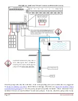
Страница 26: ...Your Wires attach them accordingly otherwise use Figure 9 1 SunRotor Pump Controller Wiring Diagram to wire the pump properly typically terminal 1 black terminal 2 blue terminal 3 brown on most SunRot...

Страница 27: ...losed switch removing one end of the sensor cable or jumper will trigger the circuit logic to turn off the pump To test the timer function set the timer to a low setting somewhere between 0 and 5 arou...

Страница 28: ...new installation 2 Make a visual inspection of the condition of the wires and connections Wires are often chewed by animals if they are not enclosed in conduit or buried Inspect the Controller 1 Open...

Страница 29: ...a choice of probe sockets The black negative probe ALWAYS goes in the COM common socket The red positive probe varies and is specified below on each of the tests FIGURE 10 1 ELECTRICAL TESTING Test P...

Страница 30: ...e a short circuit and can damage the equipment Access Open the controller cover to access the terminals The appearance of the terminals and or wiring may vary WARNING These tests pose potential shock...

Страница 31: ...the pump There should be little or no leakage over a period of hours 6 Has the pump s speed control setting been moved lower than the maximum The speed control can slow the pump down to 30 of maximum...

Страница 32: ...d remove the pump housing Remove the setscrews in the motor coupler rubber piece and unscrew the rotor from the motor shaft counter threaded turn clockwise to remove Install the new rotor and replace...

Страница 33: ...or replaced contact the SunRotor Technical Services Team at 1 866 246 7652 or 1 580 303 4015 You will be provided with an RMA number ATTENTION DO NOT send any equipment back to SunRotor Solar Products...

Страница 34: ...complements the SunRotor solar submersible pump product line Pairing the two products many of our customers are finding new and inventive ways to meet any number of water demand applications It is th...

Страница 35: ...mping http www solarpowerandpump com why go solar Database of State Incentives for Renewables Efficiency another site very useful in trying to maximize your savings http www dsireusa org Renewable Ene...

Страница 36: ......
Отзывы: