


Page 31
www.sunrotor.com
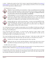
W
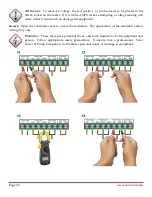
ARNING
:
The power should be turned
OFF
, as well as the pump wires removed, prior
to performing any maintenance on the pump or other equipment. Disregarding this
warning may lead to
DEATH
or
SERIOUS INJURY
. Follow any and all local, state, and
federal electrical standards and procedures and use caution.
11.1
H
ELICAL
R
OTOR
P
UMP
E
ND
M
AINTENANCE
The helical rotor pump line offers one of the easiest procedures for maintaining water demands. In
locations where abrasive minerals or sediments reside in the water source, both the rotor and stator
can eventually wear down, which in turn decreases the flow rate of the system. To replace these
parts, the pump will first need to be pulled from the well. Before starting any service, please turn off
the controller and disconnect the pump wires to prevent any high voltage current from causing
injury or death.
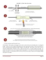
After the pump has been pulled from the well, begin dismantling the pump end. First, take off the
filter screen by removing the screws holding it secure to the pump. Next, remove the three (four on
some models) bolts holding the cast pump end in place. Once removed, access to the stator will be
available. Pull the worn stator from the rotor. Inspect the rotor for damage. If the rotor is
undamaged push a new stator on and replace the pumps end.
If the rotor is damaged, remove the three (four) bolts from the motor and remove the pump housing.
Remove the setscrews in the motor coupler (rubber piece) and unscrew the rotor from the motor shaft
(counter threaded, turn clockwise to remove). Install the new rotor and replace the setscrews in both
ends of the rubber coupling. Re-attach the pump housing, install the stator and then the pump end.
Finish with reinstalling the filter screen. In most circumstances, this will be all that is necessary to
regain the original flow rates. Set the pump back as it was in the initial installation. Once everything
is back in place, turn the pump on and observe the flow rate. There should be an observable increase
if the worn rotor/stator was the only underlying fault in the system.
11.2
C
ENTRIFUGAL
P
UMP
E
ND
M
AINTENANCE
Centrifugal pump ends currently do not offer the same convenience of field repair as the helical rotor
pump ends. Contact your Authorized SunRotor
®
Dealer or the SunRotor
®
Technical Services Team
for more information.
11.3
P
UMP
M
OTOR
R
EPAIR
All of the SunRotor
®
solar pumps—with the exception of the SR-26—have repairable pump motors.
Winding damage on the motor is currently unrepairable. If the pump motor is found to be the cause
of the system failure, contact the SunRotor
®
Technical Services Team for available rebuild options.
11.4
S
OLAR
P
ANEL
M
AINTENANCE
Depending on the region the system is installed, a few key procedures will help in maintaining the
required water demand. Many solar pump installations will be located in fields and other rural
areas, prone to the elements and dirt blown by the wind. If accessible, wipe or hose down the solar
Содержание Solar Pump
Страница 1: ...SunRotor Solar Pump Installation and Resource Manual...
Страница 36: ......