73
P
Pa
arra
am
me
ette
err
D
De
essc
crriip
pttiio
on
n
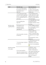
Error limit (%)**
Adjustment accuracy If the ratio of the difference between
the reactive power and the target value to the rated power
is within the set error range, the target value is reached.
Adjustment ratio (%)**
If the adjustment does not reach the set target value,
increase or decrease adjustment value according to the
set adjustment ratio, so as to reach the target value.
Reactive power
direction**
Forward: The reactive power direction of the inverter array
displayed by the meter/transformer is the same as the
actual reactive power direction.
Backward: The reactive power direction of the inverter
array displayed by the meter/transformer is opposite to
the actual reactive power direction.
Control cycle**
Time interval of delivering dispatching instructions.
Parameter range: 5~60s
Note:
The parameters noted with * refer to the parameters that need to be set only when the
Control Method is set to “Open-loop Control”.
The parameters noted with ** refer to the parameters that need to be set only when the
Control Method is set to “Closed-loop Control” .
step 4
After finishing parameter setting, click "Save" to save the operation.
-- -- E
En
nd
d
10.2.2.3 Local Power Control
If reactive dispatching instruction or dispatching target value is used as dispatching
input locally, the reactive control mode is set to "Local power control".
step 1
Click "Power control" -> "Reactive power" to enter the reactive power interface.
step 2
Set the "Reactive control mode" to "Local power control".
step 3
Set local dispatching parameters. For specific parameter description, refer to the
following table.
User Manual
Содержание Logger4000
Страница 2: ......
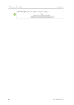
Страница 94: ...88 Bind three phase cables together every one meter 14 Appendix A Technical Data User Manual...


