


WSM.124
Section O (Body)
Open the boot lid, and from the underside pull out
the number plate lamp wire from its snap con
nector.
Support the lid with a suitable sling and remove the
retaining bolts from the prop at each side (2).
Finally, remove two nuts and washers (I) from each
hinge and take off the boot lid.
Reverse these instructions when refitting.
BOOT LID-To remove
Alpine (Fig. 31)
Support the boot lid with a suitable sling in the
open position.
Remove both the nuts, screws and washers from
each hinge (I), and the setscrews with their
washers (2) from each support prop.
Reverse these instructions when refitting.
BOOT LID LOCK-To remove
Rapier
Remove two screws with their washers (3), (Fig. 30).
The lock can now be removed by pulling out from
the inside of the boot.
The striker plate is removed by taking out the four
securing screws with their washers. The mounting
holes In the plate are elongated to provide a means
of adjustment.
To refit
Reverse the above procedure.
BOOT LID LOCK-To remove
Alpine
From below the outer edge of the boot weather
strip remove the two self-tapping screws.
Remove the tv.o screws from the rear of the top
face of the lock, and remove lock from Inside the
boot.
The striker plate is removed by taking out the four
securing screws with their washers.
The mounting holes in the plate are elongated to
provide a means of adjustment.
To refit
Reverse the above procedure.
I
st. re-issue
Page 23
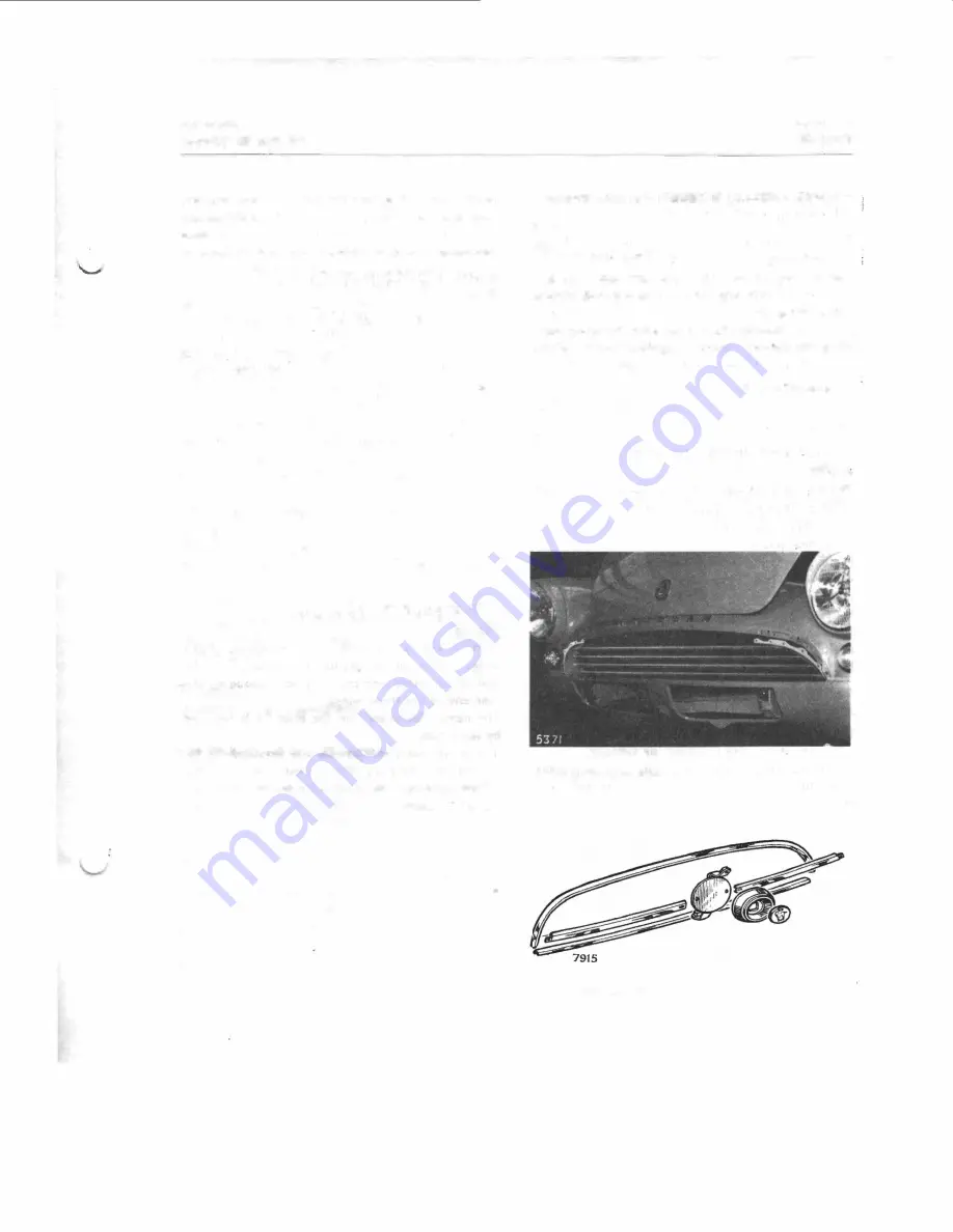
FRONT GRILLE ASSEMBLY-To remove
Rapier
Disconnect the battery.
Pull out snap connectors for side lamps arid dis
mantle the lamps. (See Section N.)
Remove three self-tapping screws (each side)
retaining the lamp body to the side grilles.
Remove the self-tapping screws securing the grille
and take off grille.
Remove nuts from the reverse side of ,each side
grille and remove grille.
To refit
Reverse the above instructions, but when refitting
the side grilles, ensure that the seals are correctly
positioned, otherwise damage may well ensure
with the final tightening of the retai'ning nuts.
Fig. 34.
Front grille assembly
(Alpine) /, //, //
I.
Fig. 34a.
Front grille assembly
(A/pine
IV)
Содержание ALPINE I SERIES: APLINE II SERIES
Страница 1: ......
Страница 42: ...1st issue Page4 0 WSM 114 Section B Engine Fig I En1lne lon11tudinal section l494c c enrlne shown J...
Страница 44: ...3rd re Issue Page 6 Fl1 3 Cylinder block and associated parts 494 c c enrine shown WSM 124 Section B Engine...
Страница 45: ...WSM 124 Section B Engine view o working parts 494 Fis 4 Exploded f 7397 c c engine shown 6th re Issue Page7...
Страница 189: ...Fis 21 Ball pin heirht checkinr fixture in position Details of items 1 to 4 In Fig 22...
Страница 208: ...Fla 3 Exploded view of rear axle Hypoid Bevel Drive...
Страница 220: ...Page 16 WSM 12 f Section G Rear Axle 0 QQ I I I I I t 0 ii 8 ts t 0 Cl 2 i J...
Страница 247: ...Page6 WSM 124 Section J Steering N Iii it...
Страница 299: ...Page 40 3 6 7 8 Fis 22 Se rvo unit exploded view Sect WSM 124 ion K Brakes 18 419 GZo 21...
Страница 413: ..._ PRINTED IN ENGLAND 9Y WREN PRINTING CQ LTD LONDON...