52
Netra ft 1800 Installation Guide • February 1999
▼
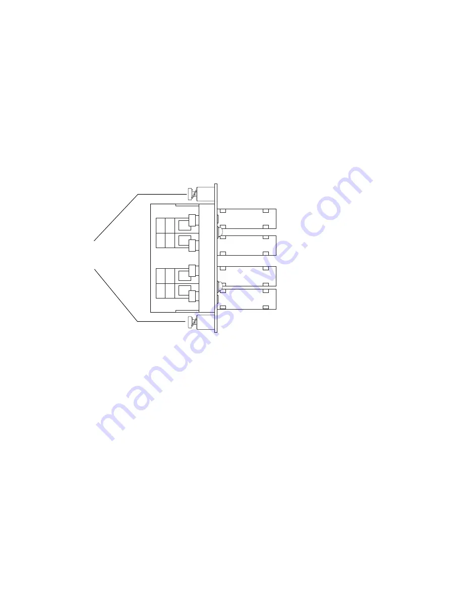
To Assemble the Power Inlet and Leads
1. Insert the socket in the appropriate slot on the motherboard.
The socket can only be inserted one way round. The label on the front of the filter
indicates the correct orientation.
2. Tighten the captive spring-loaded screws, preferably finger-tight only.
If you use a screwdriver, these screws should be tightened no more than 6 in-lbf
(0.68 Nm). Refer to
FIGURE 3-5
.
FIGURE 3-5
Power Connector Wiring Polarity and Securing Screws
3. Strip 9mm of insulation from boths ends of each power lead.
The connectors will not accommodate leads of greater than 8 AWG (6 mm
2
).
–
Negative A
–
Negative B
+
RETURN B
+
RETURN A
Inlet filter
securing
screws
Содержание Netra ft 1800
Страница 6: ...vi Netra ft 1800 Installation Guide February 1999 ...
Страница 10: ...x Netra ft 1800 Installation Guide February 1999 ...
Страница 40: ...26 Netra ft 1800 Installation Guide February 1999 FIGURE 2 12 Removing a CPUset Module ...
Страница 41: ...Chapter 2 Hardware Installation 27 CAF Modules FIGURE 2 13 Removing a CAF ...
Страница 42: ...28 Netra ft 1800 Installation Guide February 1999 PCI Modules FIGURE 2 14 Removing a PCI Card Carrier ...
Страница 43: ...Chapter 2 Hardware Installation 29 PSU Modules FIGURE 2 15 Removing a Power Supply ...
Страница 45: ...Chapter 2 Hardware Installation 31 FIGURE 2 16 Removing an RMM Module ...
Страница 56: ...42 Netra ft 1800 Installation Guide February 1999 ...
Страница 90: ...76 Netra ft 1800 Installation Guide February 1999 W weight empty chassis 6 maximum 2 removable modules 6 ...


