


14
Netra ft 1800 Installation Guide • February 1999
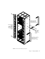
The sides of the system chassis are provided with tapped screwholes as shown in
FIGURE 2-2
.
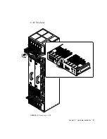
FIGURE 2-2
Location Matrix For Mounting Flange Screws (19-inch rack)
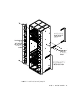
The front flanges (see
FIGURE 2-6
on page 17) are screwed to holes in column C or
column D. Use column B only if the rear flanges are not going to be used.
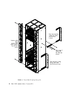
The support rails (see
FIGURE 2-7
on page 19) are screwed to holes A and B in rows 1,
4, 7 and 10. The spacers provided must be used between the rails and the chassis to
prevent the rails being fouled by the rivets in the chassis metalwork.
Front of system
Rear of system
A
B
C
D
1
2
3
4
5
6
7
8
9
10
Row numbers
Columns
Support rails
(340-5484)
Содержание Netra ft 1800
Страница 6: ...vi Netra ft 1800 Installation Guide February 1999 ...
Страница 10: ...x Netra ft 1800 Installation Guide February 1999 ...
Страница 40: ...26 Netra ft 1800 Installation Guide February 1999 FIGURE 2 12 Removing a CPUset Module ...
Страница 41: ...Chapter 2 Hardware Installation 27 CAF Modules FIGURE 2 13 Removing a CAF ...
Страница 42: ...28 Netra ft 1800 Installation Guide February 1999 PCI Modules FIGURE 2 14 Removing a PCI Card Carrier ...
Страница 43: ...Chapter 2 Hardware Installation 29 PSU Modules FIGURE 2 15 Removing a Power Supply ...
Страница 45: ...Chapter 2 Hardware Installation 31 FIGURE 2 16 Removing an RMM Module ...
Страница 56: ...42 Netra ft 1800 Installation Guide February 1999 ...
Страница 90: ...76 Netra ft 1800 Installation Guide February 1999 W weight empty chassis 6 maximum 2 removable modules 6 ...