Página 12 de 19
CONTROL PANEL SULZER APC 1/2B
USER GUIDE
Rev.13 (2018/08/30)
3.2.
SAFETY FACTORS
It is very important to correctly connect the signals from temperature and humidity sensors of
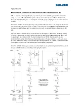
each pump to monitor its state. There are three free of potential contacts in the control panel:
one alarm from each pump and alarm status to be reset on the controller.
Remember to disconnect and lock every protection, motor circuit breaker and/or earth swith
before any maintenance action.
ALARM RESET
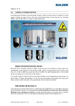
Any new alarm can be reset individually by the controller user interface also available at the door of a
button box with emergency you can reset all alarms at once. For security reasons pumping operation,
the activation level alarm float, well signposted in the box and the display of PC 242, causes a safety
reset all reset alarms that they had in PC 242, unlocked so that if the pumps automatically be blocked.
LOW LEVEL ALARM
If you use an APC box with analogue level sensor, and also shows the sump level in real time via the
display in both graphical and numerical mode, PC 242 allows you to generate alarms activating level
and potential free contact failure usually when they occur. If the active and the level drops for at least
10s of the value set for low level alarm, the controller will alarm with the text "Low". Usually the low
level alarm pumps only used for filling tanks or pumping catchment, so that by default the APC box
comes with this feature disabled, if interested activate follow the user manual PC 242 and / or
implementation guide APC 2B frame.
HIGH LEVEL ALARM
If you use an APC box with analogue level sensor, and also shows the sump level in real time via the
display in both graphical and numerical mode, PC 242 allows you to generate alarms activating level
and potential free contact failure usually when they occur. Reached or exceeded for at least 5s alarm
level set to high, the controller generates an alarm with the text "high level". By default we deliver
pictures with a value for this alarm is adjusted according to the size of the pumping equipment which
are manufactured, if you need to adjust to an optimum value for pumping well follow the user manual
PC 242 and / or implementation guide APC 2B frame.
HIGH LEVEL FLOAT ALARM
Table APC has a signal input for a high level switch to activate the semiautomatic control system to
generate alarm level (either for high level alarm drain wells). When the signal is received, the controller
indicates the alarm on the operator panel with the text "high float" and activate the floating contact
general fault. You must install this buoy above the height adjusted to high level alarm, becoming an
extra-alarm high level above that of said buoy and allowing the system to generate an alarm before
reaching semiautomatic control act. For safety is done automatically reset all alarms reset brought
forward in PC 242 when activating the alarm float.


