Sulzer ABS APC 1/2B NG Скачать руководство пользователя страница 9


Página 9 de 19 


CONTROL PANEL SULZER APC 1/2B 

 USER GUIDE 

Rev.13  (2018/08/30) 


3. 

OPERATION 

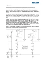
The  work  of  any  Sulzer  Pumps  Wastewater  Spain  control  panel  pursues  the  best  pump  pit  station 

operation  and  reliability  with  lowest  energy  and  maintenance  costs.  Other  designs  aspects  pursue 
avoid  labour  and  equipment  accidents,  not  allowing  manual  operation  if the  operator 

doesn’t keep in 

front of the panel, allowing the complete disconnection of the control panel from outside, etc. 
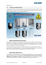


3.1. 

AUTOMATIC SEQUENCES 

A standard APC control panel works, by default, as follow. 

The main task is the pumps operation related to levels. We can set a couple of start-stop normal levels 
for  each  pumps  (or floats  in  case  of  operation  with  them). When  the  APC  works  with floats, the  start 

and stop levels are tied to the place where the floats switch on and off; when works with level sensor, 
those levels can be set from the controller display (or in remote).  

There  is  as  an  APC  control  panel  option,  to  upgrade  control  and  protections  for  an  auxiliary  device 

related to the pit like a mixer, drain pump, valve, or a cleaner system. 

The 

PC 242 user and installation guides and the document named “SETTINGS IN CONTROL PANEL 

MODEL  APC2B  COMPLETE  PROGRAMMED  FOR  USING WITH  LEVEL  FLOATS”  specific  for  this 
project,  show  in  detail  how 

PC  242  controls  and  monitors  pumps  and  pump  pit  in  an  advanced 

way

. Summarizing we can say that: 

With normal operation, when the first start level is reached (or in case of first  start float activation) 
first puma will start, when second start level is reached (or in case of second start float activation)  
second pump will start. We can set different stop levels, but if we set same stop level for all pumps 
(or working with floats, because can only connect one common stop level float to the unit), they will 
stop with a delay between stops. See 

PC 242 user guide and the document named “SETTINGS IN 

CONTROL  PANEL  MODEL  APC2B  COMPLETE  PROGRAMMED  FOR  USING  WITH  LEVEL 
FLOATS” specific for this project, for more details or to learn how to change related settings. 

Both starts  and  stops are done  with a 

delay in between

 to avoid more than two or more pumps 

were  started (or stopped) at the same time if max number of pumps allowed to run is  set over 1. 
This way we avoid electric troubles (high current loads on pump starting) and water-hammer. If you 
deactivate alternation and set max number of pumps allowed to run to 1, PC 242 will allow you to 
set the priority of the pump that must run to the pump with the highest start level. 

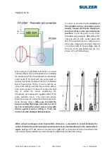
APC  can  work  both  with  level  floats  as  analogue  level  sensors.  Analogue  level  sensor  allows 
taking advantage of the PC242 advanced pump controller). We recommend to use a submersible 
hydrostatic  level  sensor  like  ABS  MD125,  MD126,  MD127  and  HSC2,  with  a  stainless  steel 
enclosure  and  a  ceramic  sensor  element, instead  of less  robust  devices  or  non-intrusive  sensors 
(like  ultrasonic  measuring  devices)  to  avoid  condensation,  bounce  signals  on  walls,  foam  effect, 
etc.  things  that  cause  measurement  errors  and  problems  in  the  own  sensor;  at  the  same  time 
allowing  an  easier  and  cheaper  maintenance,  great  robustness  and  reliability,  etc.  Pneumatic 
analogue  level  sensors  like  ABS  MD124  are  cheap,  giving  some  of  the  advantages  of  a 
submersible sensor with the drawback that only must be used when were not supposed any risk of 
the air pipe clogging. 

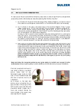
After high level float activation system warns with the proper alarm and a semi-automatic control way of 
run  pumps  is  activated  too,  starting  pumps  available  at  that  moment  till  this  float  deactivation.  This 
signal  will  even  acknowledge  all  alarms  not  acknowledged  in  the  controller,  unblocking  pumps  that 
could be blocked due false alarms. 


Содержание ABS APC 1/2B NG

Страница 1: ...nal inscrita en el Registro Mercantil de Madrid Sulzer Pumps Wastewater Spain S A Avda de la Técnica 5 28522 Rivas Vaciamadrid Madrid www sulzer com ABS APC UP TO 1 Ó 2 PUMPS CONTROL PANEL BY SULZER PUMPS WASTEWATER SPAIN S A USER GUIDE ...

Страница 2: ... 2 5 INSTALLATION RECOMMENDATIONS 2 6 CONTROL SYSTEM DESCRIPTION 3 OPERATION 3 1 AUTOMATIC SEQUENCES 3 2 SAFETY FACTORS 4 RECOMMENDED DOCUMENTS FOR READING 4 1 ELECTRICAL DRAWING 4 2 4 2FORM TO REGISTER PC242 SETTINGS 4 3 USER GUIDES fOR DEVICES RELATED TO APC CONTROL PANELS A LEVEL SENSORS MD124 MD126 MD127 USER AND INSTALLATION GUIDE B PC242 PUMPS CONTROLLER INSTALLATION GUIDE C PC242 PUMPS CONT...

Страница 3: ... to the electrical net under any circumstances Before doing it make sure the control panel is completely disconnected We recommend you to contact to an authorized specialist company to install the control panel and connect the cables its personnel must known and follow the electrical rules technically and regarding safety and recommendations To avoid loosing the guaranty only Sulzer Pumps Wastewat...

Страница 4: ...ersion and made by relays allowing working even if PC 242 were broken down in APC complete version Ready to receive a thermal sensor signal from each pump that could be bimetallic type PTC or PT100 PC 242 has an internal module to manage PTC and PT100 signals built in what allows to indicating the current temperature the sensor measures and set alarm set points Ready to receive a leakage sensor si...

Страница 5: ... to PE terminal clamp 3 Same way you could see that thermal signal cables from pumps named F0 and F1 must be connected in terminal clamps Bn F0 and Bn F1 and leakage signal cables from pumps named DI and PE must be connected in terminal clamps Bn DI and Bn PE Some small pumps have power and signal wires in the same cable in that case you will not have a PE cable for power and other for signals not...

Страница 6: ...to avoid pipe clogging as making a diagonal cut to the air pipe to have a bigger area of the side of the pipe submersed as it is shown at the left side picture When using an hydrostatic level sensor you must consider effects that could appear when installing the sensor hung from the pump pit top turbulences could make it hit itself with the sump walls or making a pendular movement that will could ...

Страница 7: ...stop if the MCB the earth leakage switch or the thermal sensor were tripped or in case of motor drive failure It is thought mainly for tests during the pump station setting up and maintenance pump checks For safety reason it returns automatically to 0 you have to keep activating the selector for the period of time you want to retain the pump running avoiding to burn the motor by accident PUMP DISA...

Страница 8: ...ES the PC 242 user and installation guides and the document named SETTINGS IN CONTROL PANEL MODEL APC2B COMPLETE PROGRAMMED FOR USING WITH LEVEL FLOATS specific for this project SEMI AUTOMATIC OPERATION SELECTOR IN AUTO APC control panel basic version has a semi automatic control system based on a PC 242 feature that runs the pumps if the high level float gets active what could happen in case of f...

Страница 9: ...one common stop level float to the unit they will stop with a delay between stops See PC 242 user guide and the document named SETTINGS IN CONTROL PANEL MODEL APC2B COMPLETE PROGRAMMED FOR USING WITH LEVEL FLOATS specific for this project for more details or to learn how to change related settings Both starts and stops are done with a delay in between to avoid more than two or more pumps were star...

Страница 10: ... apparent power power factor loads mains voltage etc PC 242 also allows you to trend graphs level curves consumption and flow pumping PC 242 enables advanced management of start and stop pumping before abrupt change in level function known as START EARLY IN CASE OF STORM It is able to start the pumps in advance to avoid overflows in the well if it detects sudden changes in level In rainwater pumps...

Страница 11: ...to work in the highest area of the well pumping more caudal less consumption so you save energy by improving the performance and reducing working hours in addition to extending the life of the pump Also allows us to make emptying the pit to levels even lower than the normal stop before passing the stretch of arrival peak hour flow in order to avoid overflows PC 242 allows REMOTE CONTROL AND PROTEC...

Страница 12: ...used for filling tanks or pumping catchment so that by default the APC box comes with this feature disabled if interested activate follow the user manual PC 242 and or implementation guide APC 2B frame HIGH LEVEL ALARM If you use an APC box with analogue level sensor and also shows the sump level in real time via the display in both graphical and numerical mode PC 242 allows you to generate alarms...

Страница 13: ...oating contact general fault This alarm also for pumps and also signalled only helps the user PUMP NOT IN AUTO NOT AVAILABLE Each pump has a switch MAN AUT 0 in front of the box to set the operating mode in which we work If after handling is left in position 0 the pump is out of service To avoid this if after 60s the selector is not passed to AUTO PC 242 advised of this fact by an alarm text not i...

Страница 14: ...of using general differential protection frame header used motor output protection to ensure the availability of pumps in pumping since in case of tripping earth leakage current in a pump or the feed cable or against nuisance tripping on start would act only protecting the pump leaving the rest available thus differential protection is especially important in pumping rainwater Fully finished in AP...

Страница 15: ...ailure of motor control element a driver may drop etc CRITIC ALARM ALL PUMPS BLOCKED If a pump is blocked by PC242 due to an alarm or switch MAN AUT 0 to 0 and for some reason it blocks the other pump pumping out of service will be completely automatic To indicate this after some time of 30s PC242 generate an alarm by the alarm text B1 and B2 blocked We can consider this alarm criticism for any pu...

Страница 16: ...APC that allows you to indicate if you want this system to act only with the pump B1 B2 with the pump or with both Once activated the alarm float pilot box excite alarm for warning buoy 2KA0 alarm and relay starting the pumps enabled it ie those selected with the selector 2S4 called SEMI COMPLETE APC and the operating mode selector to AUT Pump In Tables 23A over 2TIM1 timer is used to prevent acti...

Страница 17: ...ee contacts for remote signalling 1 alarm per pump and 1 to indicate that PC 242 has an alarm s pending reset This can be seen easily in the extract of the wiring diagram in the following figure APC offers power output buzzer light alarm ABS 9000056 or similar As you can see in the figure above connect the warning signal or you can use the floating signal is desired along with the terminals AL and...

Страница 18: ...G 4 1 ELECTRICAL DRAWING 4 2 FORM TO REGISTER PC242 SETTINGS 4 3 USER GUIDES FOR DEVICES RELATED TO APC CONTROL PANELS A LEVEL SENSORS MD124 MD126 MD127 USER AND INSTALLATION GUIDE B PC242 PUMP CONTROLLER INSTALLATION GUIDE C PC242 PUMP CONTROLLER USER GUIDE D PC242 PUMP CONTROLLER COMLI MODBUS REGISTER GUIDE ...

Страница 19: ...l with references 84004263 84004264 84004265 84004266 84004307 84004308 84004511 84004512 84004513 84004514 84004515 84004516 84004517 84004518 84004519 84004520 84004521 84004522 84004523 84004524 To which this declaration relates are in conformity with the following standards or other normative documents IEC 158 1 2 IEC 364 1 7 IEC 255 1 IEC 408 IEC 337 1 IEC 204 1 2 IEC 158 IEC 292 CE 73 23 CE ...

Отзывы: