Página 5 de 19
CONTROL PANEL SULZER APC 1/2B
USER GUIDE
Rev.13 (2018/08/30)
2.5.
INSTALLATION RECOMMENDATIONS
To make easier the job each terminal clamp for pump cable is named equal than the correspondent
pump cable, and the other cables are named considering their function. Due that:
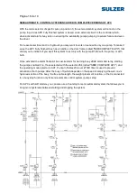
1. As it is shown in the power connection page of the electrical diagram, you have to connect
main cables in clock sequence in terminals R, S, T and PE (neutral pole is not necessary).
2. As it is shown in the power connection page of the electrical diagram, Pump 1 power
cables named as U1, V1, W1 and PE have to be connected in terminal clamps B1:U1,
B1:V1, B1:W1 and PE. Pump 2 power cables named as U1, V1, W1 y PE have to be
connected in terminal clamps B2:U1, B2:V1, B2:W1 and PE. If starting method were delta-
star, we will add U2, V2 y W2 to those indications.
In case you had to connect a motor wired for delta-star starting method in a control panel
where the way to run the pump were DOL, soft starters or VFDs, you would be able to
make the delta connection over the control panel power terminal clamps connecting cables
U1 and W2 in terminal clamp U1, cables V1 and U2 in terminal clamp V1, and cables W1
and V2 in terminal clamp W1 (of course PE cable to PE terminal clamp).
3. Same way you could see that thermal signal cables from pumps (named F0 and F1) must
be connected in terminal clamps Bn:F0 and Bn:F1; and leakage signal cables from pumps
(named DI and PE) must be connected in terminal clamps Bn:DI and Bn:PE. Some small
pumps have power and signal wires in the same cable, in that case you will not have a PE
cable for power and other for signals; nothing will happen if you remember to connect
properly the PE power cable to the PE power terminal clamp, and connect the signal
terminal clamp B1:PE to one of the control panel earth connections.
In case of pump
without bimetallic thermal sensor you should remind to make a direct connection
between terminal clamps Bn:F0 and Bn:F1for this signal, if you do not do it pump
will never run.
Read and follow the measurement device user guide before to install it and connect it to the
control panel,
mainly regarding safety recommendations and indications about a proper installation.
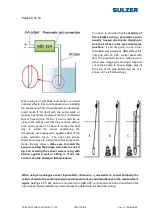
There are pump pits that have an
inlet where connect a pneumatic
sensor.
Some
kind
of
pre-
fabricated sumps made by ABS
have a T racor installed to use with
this kind of sensors and an air
compressor.
As is shown in the right side
picture, when connecting the air
pipe included in the scope of the
APC control panel with MD 124
pneumatic sensor, replace this T
racor and connect directly the
racor included in the supply (only
when less than 10 m pipe).


