Section 4
INSTALLATION
18
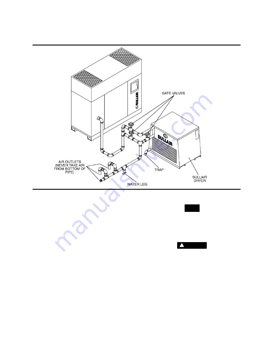
Figure 4---1 Service Air Piping with Aftercooler and Optional Air Dryer (Typical)
4.4 COUPLING ALIGNMENT CHECK
No coupling alignment is required.
4.5 FLUID LEVEL CHECK
The air compressor is also supplied with the proper
amount of fluid. However, it is necessary to check
the fluid level at installation. The level is checked by
looking at the sight glass located near the sump. If
the sump is properly filled, fluid should be visible in
the sight glass. The maximum fluid level is the level
of the filler port.
4.6
ELECTRICAL
PREPARATION--STANDARD
ELECTRO/MECHANICAL
Interior electrical wiring is performed at the factory.
Required customer wiring is minimal, but should
be done by a qualified electrician in compliance
with OSHA, National Electrical Code, and/or any
other applicable State, Federal and local electrical
codes concerning isolation switches, fused dis-
connects, etc. Sullair provides a wiring diagram for
use by the installer.
NOTE
Customer must provide electrical supply power
disconnect within sight of machine.
A few electrical checks should be made to help as-
sure that the first start---up will be trouble---free.
WARNING
!
Lethal shock hazard inside. Disconnect all power
at source before opening or servicing.
1. Check incoming voltage. Be sure that compres-
sor is wired for the correct incoming voltage.
2. Check starter for correct size, proper overload
relay, and heaters.
3. Check all electrical connections for tightness.
4. “DRY RUN” the electrical controls by discon-
necting the three (3) motor leads from the start-
er. Energize the control circuits by turning the
“O/I” STOP/START
switch to
“I” START
and
check all protective devices to be sure that they
will de---energize the starter coil when tripped.
Содержание LS-10 18KW 24KT
Страница 6: ...NOTES...
Страница 15: ...Section 2 DESCRIPTION 9 Figure 2 3 Control System...
Страница 18: ...12 NOTES...
Страница 22: ...16 NOTES...
Страница 26: ...20 NOTES...
Страница 34: ...28 NOTES...
Страница 37: ...Section 6 SUPERVISOR II 31 MESSAGE DISPLAY SYSTEM GRAPHIC DISPLAY KEYPADS Figure 6 1 Supervisor II Panel...
Страница 38: ...32 NOTES...
Страница 48: ...Section 7 MAINTENANCE 42 Figure 7 7 Piping and Instrumentation Diagram Standard...
Страница 49: ...Section 7 MAINTENANCE 43 Figure 7 8 Piping and Instrumentation Diagram Supervisor II...
Страница 50: ...44 NOTES...
Страница 52: ...Section 8 ILLUSTRATIONS AND PARTS LIST 46 8 3 MOTOR COMPRESSOR FRAME AND PARTS...
Страница 54: ...Section 8 ILLUSTRATIONS AND PARTS LIST 48 8 3 MOTOR COMPRESSOR FRAME AND PARTS...
Страница 56: ...Section 8 ILLUSTRATIONS AND PARTS LIST 50 8 4 COOLER ASSEMBLY...
Страница 58: ...Section 8 ILLUSTRATIONS AND PARTS LIST 52 8 5 AIR INLET SYSTEM...
Страница 60: ...Section 8 ILLUSTRATIONS AND PARTS LIST 54 8 6 COOLING AND LUBRICATION SYSTEM...
Страница 62: ...Section 8 ILLUSTRATIONS AND PARTS LIST 56 8 6 COOLING AND LUBRICATION SYSTEM...
Страница 68: ...Section 8 ILLUSTRATIONS AND PARTS LIST 62 8 8 CONTROL SYSTEM AND ELECTRICAL PARTS...
Страница 70: ...Section 8 ILLUSTRATIONS AND PARTS LIST 64 8 8 CONTROL SYSTEM AND ELECTRICAL PARTS...
Страница 72: ...Section 8 ILLUSTRATIONS AND PARTS LIST 66 8 9 INSTRUMENT PANEL...
Страница 76: ...Section 8 ILLUSTRATIONS AND PARTS LIST 70 8 11 DECAL GROUP 1 2 3 4 5 6 7 8 9 10 11...
Страница 78: ...Section 8 ILLUSTRATIONS AND PARTS LIST 72 8 11 DECAL GROUP 12 13 14 15 16 17 18 19 20...
Страница 80: ...Section 8 ILLUSTRATIONS AND PARTS LIST 74 8 11 DECAL GROUP 21 22 23 24 25 26 27...
Страница 82: ...Section 8 ILLUSTRATIONS AND PARTS LIST 76 8 11 DECAL GROUP ADD FULL 29 28 30 31...
Страница 84: ...Section 8 ILLUSTRATIONS AND PARTS LIST 78 8 12 WIRING DIAGRAM ELECTRO MECHANICAL AIR COOLED WATER COOLED...
Страница 85: ...Section 8 ILLUSTRATIONS AND PARTS LIST 79 8 13 WIRING DIAGRAM SUPERVISOR II DELUXE AIR COOLED WATER COOLED...
Страница 88: ...NOTES...
Страница 89: ...NOTES...


