(Mar, 2012)
CeilAiR OHS Series Installation, Operation & Maintenance Manual
Air Technology Systems, Inc.
2-14
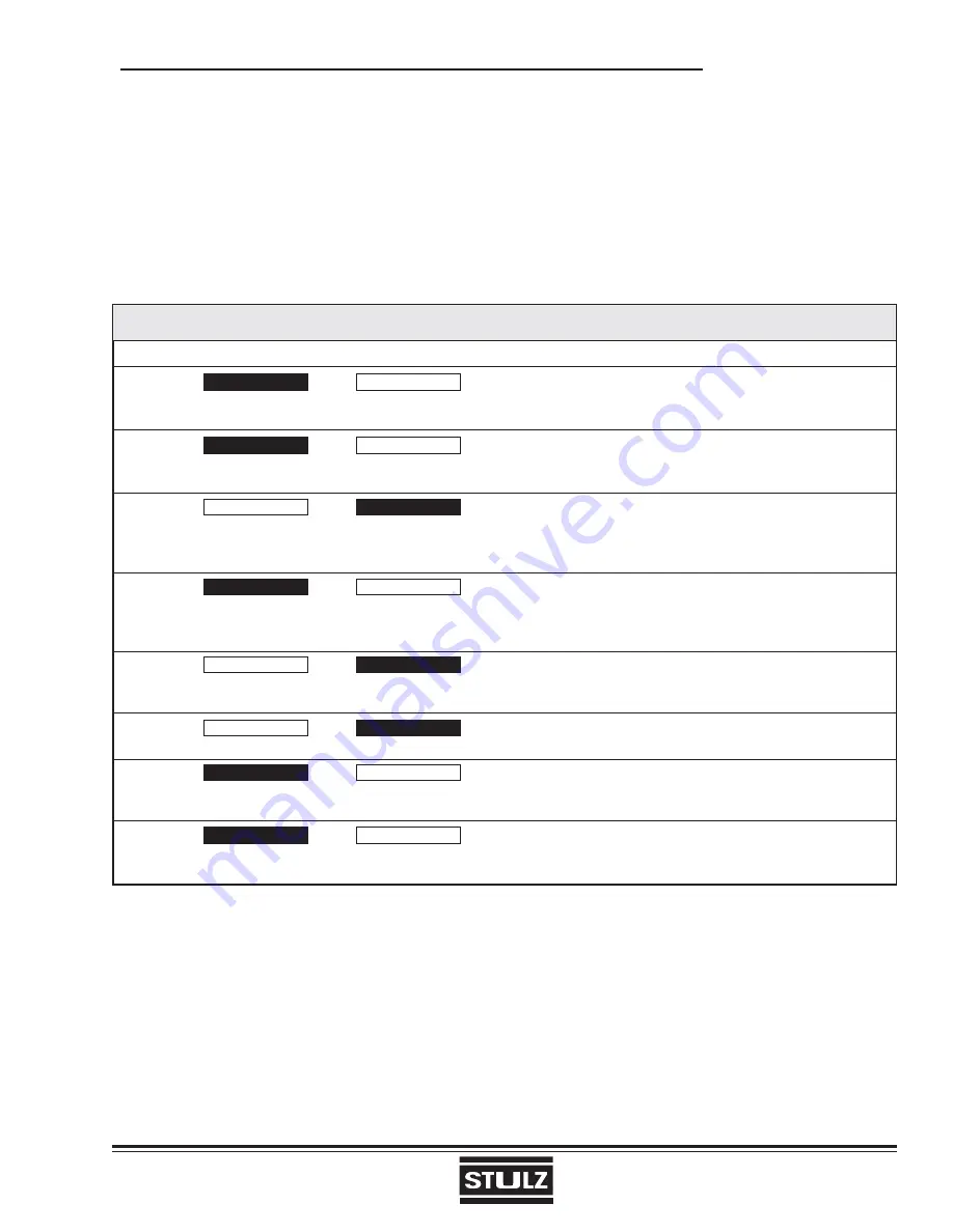
A-Tech-1.2 Dip Switch Settings
OFF ON OFF ON
1
4 Events/day
2 Events/day
Four events or two events for all seven days of the week. Four events are: Morning, Day, Evening, Night; two
events are: Day and Night.
2
Smart Fan Disabled
Smart Fan Enabled
When enabled and continuous fan has been selected, the fan terminal (G) will de-energize during the Night event
and only cycle on with the equipment.
3
4 min. on/off
2 min. on/off
Minimum time Y and W terminal will be energized, and minimum time must elapse between call. Minimum OFF
times can be overridden by raising and lowering the setpoint. Minimum ON times can only be overridden by
changing the mode.
4
Keypad unlocked
Keypad locked
In locked position only the arrow keys and outdoor temperature button will respond. When any other key is pushed
a lock appears on the display. When locked, the setpoint can only be changed by ±3° (F or C) for one hour; when
done, a hour glass will appear on the display.
5
Fan w/HT cell
Fan w/Plenum Switch
When off, the G terminal (fan) energizes with the W terminal (heat) immediately with a call for heat. When on,
the furnace controls the fan.
6
Single
Stage
Multi-Stage
In Single Stage position, terminals Y2 and W2 are locked out
7
No LCD w/LED 1
Filter LCD w/LED 1
In Filter position, when terminal LED 1 is energized a “replace fi lter” picture appears on the LCD in addition to
LED 1 illuminating.
8
No LCD w/LED 2
Wrench LCD w/LED 2
In wrench position, when terminal LED 2 is energized a picture of a wrench appears on the LCD in addition to
LED 2 illuminating.
2.7.2.3 Humidistat/Dehumidistat (Optional)
The humidistat/dehumidistat are mounted in the same manner but are wired differently. The humidistat/
dehumidistat both require two conductors for connection to the air conditioning system. The controls have pigtail
leads for splice type wire connections with twist on connectors (wire caps). Refer to the supplied electrical
schematic for proper wire terminations.
2.7.2.2 A-Tech-1.2 Programmable Thermostat
(Dual Stage Unit; See Figure 8)
Set the dip switches located on the circuit board according to the application needs. Refer to the following chart
provided for factory settings. The thermostat requires seven conductors wired to the control terminal board
located within the unit electrical box. The thermostat provides a terminal strip with box type lugs for wire connec-
tions. Refer to the supplied electrical schematic for proper wire terminations.
Содержание CeilAiR Series
Страница 1: ... Mar 2012 CeilAiR OHS Series Installation Operation Maintenance Manual Air Technology Systems Inc ...
Страница 54: ... Mar 2012 CeilAiR OHS Series Installation Operation Maintenance Manual Air Technology Systems Inc NOTES ...
Страница 56: ... Mar 2012 CeilAiR OHS Series Installation Operation Maintenance Manual Air Technology Systems Inc ...
Страница 58: ... Mar 2012 CeilAiR OHS Series Installation Operation Maintenance Manual Air Technology Systems Inc ...


