3
Overview
General instructions
Area of use/scope of delivery
Overview
General instructions................................................. 3
Illustration of boiler types 20-70............................... 4
Illustration of boiler type 60 L................................... 5
Boiler technical data................................................ 6
Boiler dimensions.................................................... 7
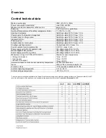
Control technical data.............................................. 8
Boiler room/air supply/installation site …..……….... 9
Checks following transport....................................... 9
Assembly
Assembly of the cladding with insulation………….. 10
Flue......................................................................... 11
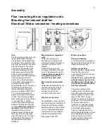
Mounting the air regulation units............................. 11
Mounting the induced draft fan….............................11
Filling and draining.................................................. 11
Heating connections.................................................11
Raising the return temperature............................... 12
Thermal discharge safety device..............................12
Mounting the O
2
probe and exhaust fume
sensor.......................................................................12
Mounting the storage tank sensor .......................... 13
Mounting the hydraulic unit .................................... 13
Mounting the control …........................................... 13
Hydraulic diagrams - overview ............................... 14
Hydraulic diagram
– system 3 ................................ 15
Electrical connection diagram ................................ 15
System 3................................................................. 16
Functional description ............................................ 16
Important instruction .............................................. 16
Hydraulic diagram
– system 3.1 ............................. 17
Electrical connection diagram ................................ 17
System 3.1.............................................................. 18
Function description …........................................... 18
Important instruction .............................................. 18
Settings for system 3 ..............................................19
Table for noting system settings ............................ 20
Aggregate test ...................................................... ..20
Commissioning
Instruction/commissioning/handover ...................... 21
Commissioning the control ..................................... 21
Setting the boiler water temperature ...................... 21
Commissioning the boiler........................................ 22
Heating up/adding fuel ........................................... 22
Circuit diagram ....................................................... 23
Short operating instructions: lambda control OFF .. 24
Short operating instructions: lambda control ON..... 25
Maintenance
Boiler maintenance ................................................ 26
Malfunctions
Troubleshooting ..................................................... 26
General instructions
Installation, assembly, electrical
connections and first commissioning
are tasks for a qualified expert. He is
responsible for ensuring proper
implementation.
Explanation of our warranty
conditions.
We have to exclude our warranty for
damages occurring due to the
following reasons:
- inappropriate or improper use
- incorrect assembly resp.
commissioning by the purchaser or
a third party, including the fitting of
third party parts
- operation of the system with
excessive pressure.
The prerequisites for the provision of
a warranty are:
- correct operation of the boiler
- operation of the system within the
performance limits specified by the
manufacturer
- use of suitable fuels.
- the return of the completed
commissioning protocol to
thermostrom Energietechnik
Gesellschaft mbH.
Instruction for the user
The system will retain its safety and
functions if it is serviced regularly
every year.
Fields of use
Boilers from the Turbotec series are
suitable and approved for use as heat
generators in hot water heating
systems with a permissible flow
temperature of up to 100 °C. They
can be installed in open and closed
systems according to DIN 4751,
sheets 1 and 2, or ÖNORM B 8130
and B 8131.
Scope and method of delivery
Boiler body loose. Cladding with
insulation in a carton. Lambda control,
storage tank sensor, exhaust fume
sensor, O
2
probe, induced draft fan,
air regulator units, ash tray,
commissioning protocol, installation
and operating manual stored inside
the filling chamber.
Содержание 40S-70
Страница 27: ...23 Commissioning Circuit diagram ...
Страница 29: ...24 Commissioning Short operating instructions ...
Страница 31: ......
Страница 35: ...28 Notes ...
Страница 38: ......


