background image


INSTRUCTION MANUAL 

FOR MAINTENANCE AND OPERATION  

OF ELECTRIC CONTINUOUS FLOW HEATER/MODULE  


DOSSIER 

ELECTRIC CONTINUOUS FLOW HEATER/MODULE


“Deluxe BH” 207, 209, 312, 315, 318, 321, 324  

  “Deluxe Module BK” 336, 350  

“Deluxe Combi BH” 209 E, 212 E, 312 E, 315 E, 318 E, 321 E, 324 E 


Burgas 8000, 47 Slivnitsa Street; Ph.: 056/ 81 46 81, 056/ 81 42 15 

E – mail: [email protected]


www.ecotermal.com


Содержание Deluxe BH 207

Страница 1: ...R MODULE DOSSIER ELECTRIC CONTINUOUS FLOW HEATER MODULE Deluxe BH 207 209 312 315 318 321 324 Deluxe Module BK 336 350 Deluxe Combi BH 209 E 212 E 312 E 315 E 318 E 321 E 324 E Burgas 8000 47 Slivnitsa Street Ph 056 81 46 81 056 81 42 15 E mail sales ecotermal bg com www ecotermal com ...

Страница 2: ...agram heating system only 4 Heater diagram heating system and domestic hot water system 4 Electric diagram single phase model 5 Electric diagram three phase model 6 Control system heater for a heating system only 7 Control system heater for a heating system and a domestic hot water system 7 Technical parameters 8 9 4 Installation manual 9 5 Connection to the power system 10 12 6 Connection to the ...

Страница 3: ...s Preventive maintenance shall be provided at least once a year to ensure proper performance safety and long service life for the heater Vendor shall not be liable for any damage attributable to non professional installation and or disregard to the recommendations and or the operating instructions no maintenance services will be due in that case Heating systems shall be provided with vent valves i...

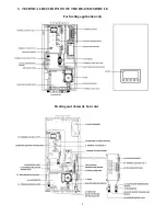
Страница 4: ...4 3 TECHNICAL DESCRIPTION OF THE HEATER MODULE For heating application only Heating and domestic hot water ...

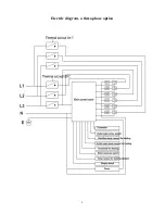
Страница 5: ...5 Electric diagram a single phase option ...

Страница 6: ...6 Electric diagram a three phase option ...

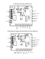
Страница 7: ...7 Control diagram heating application only Control diagram heating system and domestic hot water application ...

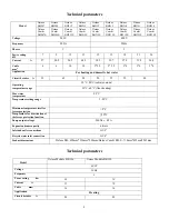
Страница 8: ... Application For heating and domestic hot water Circuit breaker A 32 63 80 20 25 32 40 Operating temperature range 30 C 80 C radiator mode 30 C 60 C floor heating Max water temperature 85 C Temperature setting range 5 20 C Minimum temperature level for freeze protection 8 C Temperature for deactivation of the freeze protection function 10 C Pump output voltage 240Vac 0 5A Expansion drum capacity 6...

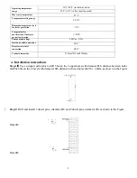
Страница 9: ...ameter Φ8 and 2 dowel pins diameter Φ6 as shown in the Figure Hole Φ8 Hole Φ6 Operating temperature range 30 C 80 C in radiator mode 30 C 60 C in floor heating mode Max water temperature 85 C Temperature setting range 5 20 C Minimum temperature level for freeze protection 8 C Temperature for deactivation of the freeze protection function 10C Pump output voltage 240Vac 0 5A Inlet and outlet connect...

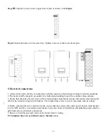
Страница 10: ... 3 Ensure that the ends of metal wires to the terminal strips circuit breakers make full contact when laying the cable to the terminal strips circuit breakers Then tighten the screws to ensure maximum current voltage 4 Before commencement of electrical works ensure that the switch of the main power board circuit breaker is in the OFF position to avoid any hazards due to electric shock all installa...

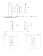
Страница 11: ... cable size open the relevant hole numbers in the cover Cables can also be installed through a major common hole 5 3 Connect the L N E cables as per the instructions shown on the sticker Single phase models Three phase models ...

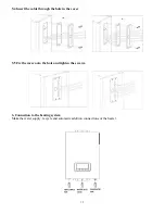
Страница 12: ...ert the cable through the hole in the cover 5 5 Fix the cover onto the hole and tighten the screws 6 Connection to the heating system Make the water supply recycle and automatic addition connections of the heater ...

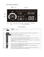
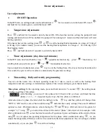
Страница 13: ...setting was achieved 6 Displays temperature difference between heating fluid outlet temperature and heating fluid inlet temperature 7 This icon will go on to indicate that the pump is running 8 This icon will go on to indicate that the heater is running with antifreeze protection function enabled This mode is enabled when temperature falls below 8 С 9 This icon will go on to indicate that the heat...

Страница 14: ...he parameter will increase by 1 step Touch and hold down Select the required time interval the parameter will keep increasing System parameters setting or mode setting Touch once With every touch the parameters will increase by 1 step Touch and hold down The parameter will keep increasing Real time setting state Touch once With every touch the parameters will decrease by 1 step Touch and hold down...

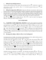
Страница 15: ...ly the parameter settings Time setting Daily and weekly programming You can set the heater for a 24 hour operating mode for 7 days a week as well as the heating fluid temperature and time settings A detailed description of the various settings is given herein below Time phase setting In the operating mode press and hold down for 5 seconds the setting mode switches to setting of time phase starts b...

Страница 16: ... using the key for the left position and key for the right position Figures 1 to 9 will be displayed first then letters After selection of bE confirm using the key Submenus will be displayed using the key go to the TC submenu the icon will be displayed then after that make adjustments using the and keys Display 00 means that no wired controller is connected Display 01 means that there is a wired c...

Страница 17: ...tion of bE confirm using the key Submenus will be displayed using the key go to submenu SB to display the pump icon then make adjustments using the and keys Display 00 means that the controller automatically controls the pump display 01 means that the pump is in continuous operation while the heater is running Flow meter disabled Flow rate sensor performance can be adjusted In the OFF mode press a...

Страница 18: ... models MODEL ACCESSORIES Deluxe BH Deluxe Module BK Deluxe Combi BH E Expansion drum Circulation pump Filter Safety relief valve Low pressure protection Emergency shutdown thermostat Vent valve Domestic hot water Mounting brackets ...

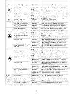
Страница 19: ...r for domestic hot water A Tighten the connection between temperature sensor and PCB B Replace the temperature sensor Contact the local service provider E7 Available only for domestic hot water mode Outlet temperature 73ºC for domestic hot water mode Reduce the temperature setting increase water flow rate Leakage of connection at water inlet outlet heating fluid A Loose connection B Damaged sealin...

Страница 20: ...ic heater module is intended for installation using wall mount brackets only for walls that can support its weight Select the location for this electric heater module to ensure easy access distances as per the process requirements on all four sides 1 This heater module shall be installed in a location that can ensure convenient conditions for maintenance easy access to the device and possibility t...

Отзывы: