4
Overview
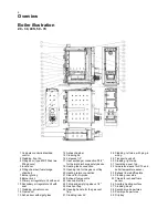
Boiler illustration
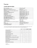
20 - 30, 40S, 50 - 70
1 Computer-controlled lambda
control
2 Cladding, front lid
4 Filling door (type 40S-70has two
filling doors)
5 Inner door
6 Filling chamber (fuel storage
chamber)
7 Burner grating
8 Burner brick
9 Primary air regulator unit with seal
10 Secondary air regulator unit with
seal
11 Cladding, actuator cover
12 Flame duct
13 Ashes door with sight glass
14 Ashes chamber
15 Cleaning lid
16 2 sleeves 1/2”
17
Heat exchanger connection R1/2”
for thermal discharge safety device
18 Heating feed connection
19 Opening rod for the gas vent flap
20 Heating return connection
21 Sleeve for O
2
probe
22 Exhaust fume nozzle
23 Induced draft fan
24 Filling and emptying sleeve 1/2"
25 Gas vent flap
26 Opening handle for the gas vent
flap
27 Cladding, rear lid
28 Cladding, left side, with plug-in
wiring
29 Transport eye bolt
30 Cladding, right side
31 Insulating panel, top
32 Immersion sleeve for STL and
boiler temperature sensor
33 Exhaust fume baffle plate
34 Cladding, rear side
35 Thread for exhaust fume
sensor
36 Ancillary heating surface
37 Cladding, base
38 Secondary air apertures
39 Primary air apertures
40 Drip tray
Содержание 40S-70
Страница 27: ...23 Commissioning Circuit diagram ...
Страница 29: ...24 Commissioning Short operating instructions ...
Страница 31: ......
Страница 35: ...28 Notes ...
Страница 38: ......


