31
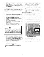
HIGH PRESSURE CUTOUT TEST
A.
Connect a gauge to the Schrader valve on the
discharge line.
B.
Disconnect cooling:
In a water-cooled machine, shut off the water
supply.
In an air-cooled machine, shut off the fan motor in
the IntelliTec2 control. Refer to Section 4.6 for
details.
For the hopper fan, disconnect the fan motor.
C.
High pressure cutout should trip when pressure
reaches 445 psig ±9 in the freezing cylinder system
and 405 psig in the hopper system.
HIGH PRESSURE CUTOUT REMOVAL
A.
Remove the side panel.
B.
Recover refrigerant charge per instructions in
Section 5.2.
C.
Leave the suction and discharge ports open to
prevent pressure buildup during removal.
D.
Unsweat capillary tube from suction line.
E.
Disconnect terminals from high pressure cutout.
HIGH PRESSURE CUTOUT REPLACEMENT
A.
With the suction and discharge ports open, braze
the capillary tube to the discharge line.
C.
Replace the drier per the instructions in Section
5.9.
D.
Braze bulb into place on suction line.
E.
Evacuate the system per the instructions in Section
5.2.
F.
Recharge the system per the instructions in Section
5.3.
G.
Connect the terminals to the high pressure cutout.
H.
Attach the high pressure cutout using the two
screws with star washers.
E. EVAPORATOR PRESSURE REGULATOR (EPR)
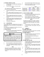
There is one EPR in the refrigeration system (Refer to
Figure 5-9). It is located on the suction line of the hopper
evaporators and regulates evaporator refrigerant pressure.
EPR TEST AND ADJUSTMENT
Adjustment to the EPR must be made when the hopper
refrigeration is running
A.
Disconnect the machine from electrical supply
before removing any panels for servicing.
B.
Remove the left side panel.
C.
Connect a gauge to the Schrader valve on the
suction line between the hopper evaporators and
the EPR.
D.
Connect power to the machine.
E.
Turn the machine on by pressing the Main Power
Off/On button. Listen for the hopper compressor to
start.
F.
The gauge should read 25-26 psig. If it does not,
then adjustment is needed.
G.
Remove the plastic cap and loosen the locknut on
the EPR. Using a small screwdriver, turn the
adjustment screw counterclockwise 1/2 turn, then
adjust as necessary. Turn the valve stem clockwise
for higher pressure or counterclockwise for lower
pressure.
H.
Allow the system to stabilize for 5 minutes to
ensure pressure remains stable.
EPR REMOVAL
A.
Remove the left side panel.
B.
Recover refrigerant charge per instructions in
Section 5.2.
C.
Leave the suction and discharge ports open to
prevent pressure buildup during EPR removal.
D.
Unsweat the EPR and remove.
Figure 5-9 EPR Valve
WARNING
Hazardous voltage
Make sure the machine is off when disassembling
for servicing. The machine must be disconnected
from electrical supply before removing any access
panel. Failure to disconnect power before servicing
could result in death or serious injury.
Содержание O231
Страница 1: ...Model O231 SERVICE MANUAL Manual No 513646 Sept 2010 ...
Страница 2: ......
Страница 10: ...4 ...
Страница 12: ...6 ...
Страница 20: ...14 ...
Страница 30: ...24 ...
Страница 58: ...52 8 7 WIRING DIAGRAMS ...
Страница 59: ...53 ...
Страница 60: ...54 ...
Страница 61: ...55 ...
Страница 62: ...56 ...


