30
E.
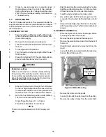
If the pressure reading is lower than expected,
check to see if there is a low refrigerant charge or
if there is a restriction in the system.
NOTE
The AXV is the LAST component to adjust in the
refrigeration system.
F.
The AXV can be adjusted after the steps above are
completed. When adjusting, do not turn the valve
over 1/4 turn (90°). Turn the valve stem clockwise
to decrease the evaporator pressure or
counterclockwise to increase the evaporator
pressure.
AXV REMOVAL
A.
Disconnect the machine from electrical supply
before removing any panels for servicing. Remove
the the front panel.
B.
Recover refrigerant charge per instructions in
Section 5.2.
C.
Leave the suction and discharge ports open to
prevent pressure buildup during AXV removal.
D.
Remove any insulation from the AXV and immediate
surrounding lines.
E.
Apply a heat sink (wet cloth) to the valve dome.
F.
Unsweat the AXV and remove.
AXV REPLACEMENT
To replace the AXV, perform the following procedures:
A.
Position the AXV, with a heat sink, into the
system.
B.
With the suction and discharge ports open, braze
the AXV into the system.
C.
Remove the heat sink from the AXV.
E.
Replace insulation to the AXV and surrounding
lines.
F.
Replace the drier per the instructions in Section
5.9.
G.
Evacuate the system per the instructions in Section
5.2.
H.
Recharge the system per the instructions in Section
5.3.
C. CHECK VALVE
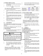
The machine has 2 magnetic check valves (Refer to Figure
5-6). Each valve is positioned in the suction line and
prevents backflow of refrigerant into the evaporator. If there
is reversed flow, the product in the freezing cylinder softens
and liquid refrigerant can flood into the compressor on
startup.
If a check valve needs to be replaced, use a heat sink (wet
cloth) when installing the new valve to prevent damage.
D. HIGH PRESSURE CUTOUT
There is a high pressure cutout for each freezing cylinder
(Fig 5-7) and one for the hopper refrigeration (Fig 5-8). The
high pressure cutout stops the compressor if the discharge
pressure reaches the cutout, 445 psig for the freezing
cylinders and 405 psig for the hopper.
The high pressure cutout for the freezing cylinders auto-
matically reset. The cutout for the hopper refrigeration is a
manual reset located behind the back panel.
Figure 5-7 High Pressure Cutout
Freezing Cylinders
Figure 5-6 Check Valve
Figure 5-8 High Pressure Cutout
Hopper Refirgeration
Содержание O231
Страница 1: ...Model O231 SERVICE MANUAL Manual No 513646 Sept 2010 ...
Страница 2: ......
Страница 10: ...4 ...
Страница 12: ...6 ...
Страница 20: ...14 ...
Страница 30: ...24 ...
Страница 58: ...52 8 7 WIRING DIAGRAMS ...
Страница 59: ...53 ...
Страница 60: ...54 ...
Страница 61: ...55 ...
Страница 62: ...56 ...


