


Transistor Servo-Drive TV6.2
22
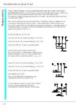
Adjustments -
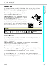
Command value
The command value input X1:26c (X1:4) is dimensioned for a voltage command
value of ±10V .
The command value is generated by using the internal voltage supplies of
+10V across X1:28c (X1:3) and -10V across X1:24c (X1:5) or by applying a com-
mand value voltage from a PLC or CNC.
The input resistance is 50 kΩ.
The relay contacts of the command value circuitry must be gold or reed con-
tacts.
When using the internal command value supply the switch S2:K2 must be closed
(ON) (rf. to device ground).
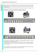
Note:
If the supplementary command value input at terminal no. 17 is
not used, it must be bridged to GND
(terminal no. 23, 24). (Rf. to page 23)
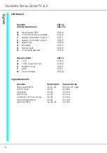
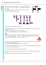
Output X1:28c (X1:3) +10V/5mA
Output X1:24c (X1:5) -10V/5mA
Output X1:18c (X1:8) device ground GND
Input X1:26c (X1:4) command value 0 to ±10V
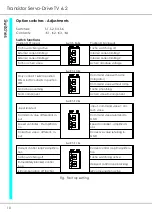
The rotation direction is changed by means of the re-
lay contacts d1 and d2.
Stationary condition when d1 and d2 are open.
Speed adjustments by means of the poti P
com.val.
Potentiometer resistance 5 to 10kΩ
Command value voltage 0 to ± 10V.
Switch S2:K2 closed.
Input X1:26c (X1:4) command value
Input X1:18c (X1:8) command value
Voltage X1:26c - X1:18c 0 to ± 10V
Input resistance 50 kΩ
Differential input when switch S2:K2 is open.
When using the command value input as
differential input, the device ground (X2:23)
must be earthed.
Содержание TV 6.2
Страница 12: ...Transistor Servo Drive TV 6 2 12 ...
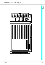
Страница 13: ...TV6 2 13 3 Mechanical Installation ...
Страница 14: ...Transistor Servo Drive TV 6 2 14 ...
Страница 15: ...TV6 2 15 3 Mechanical Installation ...
Страница 17: ...TV6 2 17 4 Adjustments Anschluss Kompaktgerät Anschluss Mehrachskombination ...
Страница 38: ...Transistor Servo Drive TV6 2 38 ...
Страница 39: ...TV6 2 39 8 Circuit Diagrams ...
Страница 40: ...Transistor Servo Drive TV6 2 40 ...
Страница 41: ...TV6 2 41 8 Circuit Diagrams ...


