


TV6.2
9
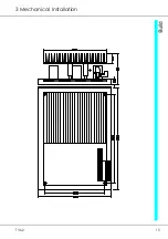
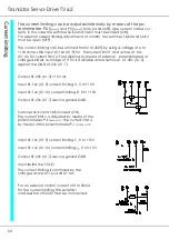
2 Electrical Installation
Connection terminals X1, X2, and connectors X
1
Function
Terminal no. Connector no.
+ 15V (for enable)
X1: 1
X1: 32c
Enable input (+10V to +30V)
X1: 2
X1: 30c
+ 10V (for command value)
X1: 3
X1: 28c
Command value input (signal)
X1: 4
X1: 26c
- 10V (for command value)
X1: 5
X1: 24c
Tacho input(GND)device ground X1: 6
X1: 22c
Tacho input (signal)
X1: 7
X1: 20c
Command value input (GND)
X1: 8
X1: 18c
External current limit I1
X1: 9
X1: 16c
External current limit I2
X1: 10
X1: 14c
Power voltage
X1: 12
X1: 10ac
Power voltage
X1: 14
X1: 6ac
Motor connection
X1: 15
X1: 4ac
Motor connection
X1: 16
X1: 2ac
Command value-additional input X2: 17
X1: 32a
Overload signal
X2: 18
X1: 30a
Tacho fault signal
X2: 19
X1: 28a
Current (I-actual)
X2: 20
X1: 26a
Drive ready (BTB)
X2: 21
X1: 24a
Drive ready (BTB)
X2: 22
X1: 22a
Device ground (GND)
X2: 23
X1: 20a
Device ground (GND)
X2: 24
X1: 18a
Signal - stationary condition
X2: 25
X1: 16a
Over-temperature
X2: 26
X1: 14a
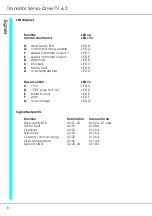
Test point jack X4
Function
Connector no.
n - command value
(at the output of the diff. amplifier
X4: 1
n - command value
(at the input of the speed controller)
X4: 2
I - command value
X4: 3
+ 10V reference
X4: 4
- 10V reference
X4: 5
I - actual value
X4: 6
n - actual value (at the output of the divider)
X4: 7
enable
X4: 8
free
X4: 9
device ground GND
X4:10
Содержание TV 6.2
Страница 12: ...Transistor Servo Drive TV 6 2 12 ...
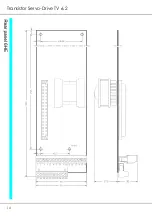
Страница 13: ...TV6 2 13 3 Mechanical Installation ...
Страница 14: ...Transistor Servo Drive TV 6 2 14 ...
Страница 15: ...TV6 2 15 3 Mechanical Installation ...
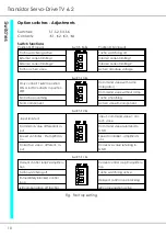
Страница 17: ...TV6 2 17 4 Adjustments Anschluss Kompaktgerät Anschluss Mehrachskombination ...
Страница 38: ...Transistor Servo Drive TV6 2 38 ...
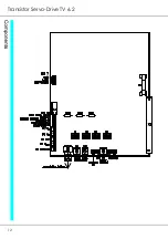
Страница 39: ...TV6 2 39 8 Circuit Diagrams ...
Страница 40: ...Transistor Servo Drive TV6 2 40 ...
Страница 41: ...TV6 2 41 8 Circuit Diagrams ...


