


TV6.2
31
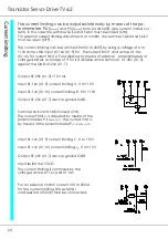
4 Adjustments
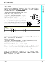
The effect of the actual value differentiation can be measured at the connec-
tor no. X4:7 by means of an oscilloscope.
When the motor is connected and enabled a command value jump of 50% is
set and the actual value response is examined.
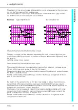
Example:
high amplification
low amplification
The switches S6:K2 and S2:K3 must be closed.
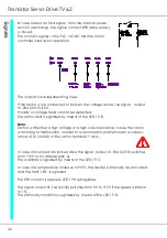
The peak current can be adjusted separately for both current directions bet-
ween 0 and 200% type current by means of the potentiometers P5(Imax1) and
P6 (Imax2).
right full scale = max. current
The switches S6:K2 and S2:K3 must be open.
The current limiting can be adjusted by means of an external voltage across
X1:16c (X1:9) I
max1
and across X1:14c (X1:10) Imax2.
The external signal can be attenuated by means of the internal potentiometers
P5 (Imax1) and P6 (Imax2) .
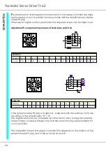
For the combination of speed-torque control the torque is adjusted at the in-
puts X1:16c and X1:14c.
By means of the potentiometer P7 (I
D
) it is possible to adjust the continuous
current for both torque directions between 2 and 100% of the type current.
The reset time of the current limit from peak to continuous current depends on
the previous continuous current demand.
This means, that a long peak current time (approx. 2 s) is available with a low
current and that in case of a high continuous current (80% type current) the
peak current time is reduced to approx. 0.5 s.
For the combination of speed-torque control the torque is adjusted at the
inputs X1:16c and X1:14c.
Содержание TV 6.2
Страница 12: ...Transistor Servo Drive TV 6 2 12 ...
Страница 13: ...TV6 2 13 3 Mechanical Installation ...
Страница 14: ...Transistor Servo Drive TV 6 2 14 ...
Страница 15: ...TV6 2 15 3 Mechanical Installation ...
Страница 17: ...TV6 2 17 4 Adjustments Anschluss Kompaktgerät Anschluss Mehrachskombination ...
Страница 38: ...Transistor Servo Drive TV6 2 38 ...
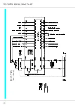
Страница 39: ...TV6 2 39 8 Circuit Diagrams ...
Страница 40: ...Transistor Servo Drive TV6 2 40 ...
Страница 41: ...TV6 2 41 8 Circuit Diagrams ...