


Transistor Servo-Drive TV6.2
18
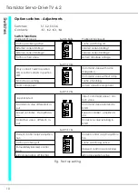
Adjustments -
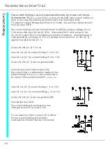
Power connection
Note:
The order of the connections to the connector numbers or screw terminals is ob-
ligatory.
All further advices are non-obligatory.
The input and output conductors may be altered or supplemented in accor-
dance with the electrical standards.
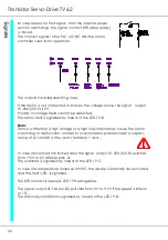
An isolating transformer is used as
power transformer
. Several TV6.2 devices can
be connected in parallel to one transformer if the device input has a 2-pole
protection and circuitry.
The power connection must not be grounded
. The ‘device ground’ of each de-
vice must be connected with at least 2.5 mm².
In case of very wide control ranges or different motor voltages separated win-
dings are advisable.
The power ratios of the transformer corresponds to the sum of all simultaneously
applied continuous motor currents. Please note that the relay contacts prece-
ding the transformer must be rated to its switch-on current.
The transformer is to be protected with slow fuses.
The motor can be connected by means of an armature choke to the terminals
X1:15 and X1:16.
The choke inductance should be approx. 0.5 mH. It is only used to reduce spuri-
ous emissions as well as the collector voltage across the motor. It is not required
to protect the TV6.2 device.
The motor lines are only allowed to be switched when the mains current is dis-
abled. Any switching-off when connected to current will cause arcing.
Any switching-on when the controller is enabled may damage the motor.
Содержание TV 6.2
Страница 12: ...Transistor Servo Drive TV 6 2 12 ...
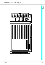
Страница 13: ...TV6 2 13 3 Mechanical Installation ...
Страница 14: ...Transistor Servo Drive TV 6 2 14 ...
Страница 15: ...TV6 2 15 3 Mechanical Installation ...
Страница 17: ...TV6 2 17 4 Adjustments Anschluss Kompaktgerät Anschluss Mehrachskombination ...
Страница 38: ...Transistor Servo Drive TV6 2 38 ...
Страница 39: ...TV6 2 39 8 Circuit Diagrams ...
Страница 40: ...Transistor Servo Drive TV6 2 40 ...
Страница 41: ...TV6 2 41 8 Circuit Diagrams ...


