


Digital Output Module Relay and Sockets for Installation in Zone 1 / Div. 1 Series 9477/12 / 9490
2
201
-
-
·BA00·III·en·0
201526 / 9477610310
www.stahl-ex.co
P2
perating Instructions for the IS1-System
IS1 I/O-Modules
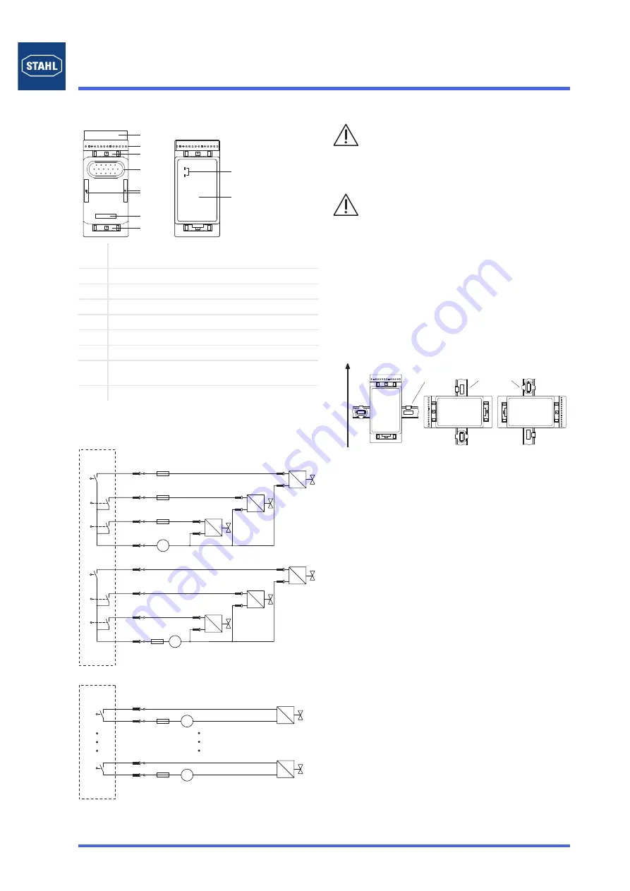
Components
Overview
12254E00
Ex e terminal
The socket has 16 terminals for connecting the field cables.
Terminal assignment
9477/12-06-12 on socket 9490/1.-34:
12255E02
9477/12-08-12 on socket 9490/1.-33:
12256E02
Designing
✗
The module is intended for IS 1 field stations and can be
installed in hazardous areas of Zone 1/Division 1, Zone 2/
Division 2 or in the safe area.
✗
For installation in hazardous areas the module must be fitted
into an enclosure which is certified according to the
increased safety requirements (e.g. R. STAHL type 8126).
✗
The module is installed for designated use on the
IS1 BusRail.
✗
A mixed arrangement of the BusRail with different
I/O modules is permitted.
✗
Operation of the module is only admissible in three assembly
positions:
assembly direction above:
✗
Only non intrinsically-safe circuits can be connected to the
Ex e terminal.
✗
Work at the connected electric circuits is permitted only if
de-energised.
✗
After connection of the field circuits to the Ex e terminal
ensure ingress protection IP30.
✗
A corresponding instruction plate must be placed on the
enclosure.
✗
Conductors with a small cross-section must be connected
with insulated end covering sleeves.
✗
At the socket 9490/11-34 unused connection terminals must
be protected against accidental contact (e.g. by means of a
special cover or an appropriate sealing of cable entries).
✗
The screens on the fieldbus cabling must be connected to the
equipotential bonding system of the hazardous area! For this
purpose the screens on the fieldbus cabling must be
connected to the screen bars installed in the enclosures as
close as possible to the entry point! The screen bars must
also be connected to the mounting plate close to the entry
points for the fieldbus cabling by the shortest possible route!
1
Protective cover (opened) to ensure ingress protection
IP30
2
Ex e terminals
3
Detent lever for removing the module from the BusRail
4
Socket for the module
5
Clamp screw
6
Socket for the module
7
Detent lever for removing the module from the BusRail
8
LED for status or fault indication (further information
see "LED indication and Troubleshooting")
9
Digital Output Module Relay
1
2
3
4
5
6
7
8
9
0
Channel
Ex e terminal
I 2 A
≤
15
V
I 2 A
≤
13
I 2 A
≤
9
11
7
V
5
I 2 A
≤
1
3
1
2
4
3
5
V
0
7
I 2 A
≤
Ex e terminal
16
15
V
I 2 A
≤
2
1
Channel
The national installation instructions
(e.g. IEC/EN 60079-14) must be observed.
Intrinsically-safe and non-intrinsically safe circuits must
not be used in a common cable duct!
Ensure that there is a distance of at least 50 mm
between connection facilities of intrinsically-safe and
non-intrinsically safe circuits!
Ensure that max. values for current, voltage and power
(see Technical Data) are observed.
The switching current of the contacts must be limited to
2 A (e.g. fuse or current limitation).
12257E00
BusRail
BusRail
Содержание IS1
Страница 13: ......


