08.02.
Reistle
2013
9400 6 031 001 1
none
FM
Kaiser
1 of 32
02
26.02.2014 Bagusch
01
22.01.2014 Bagusch
IS1 resp. IS1+ Remote I/O System
Overview
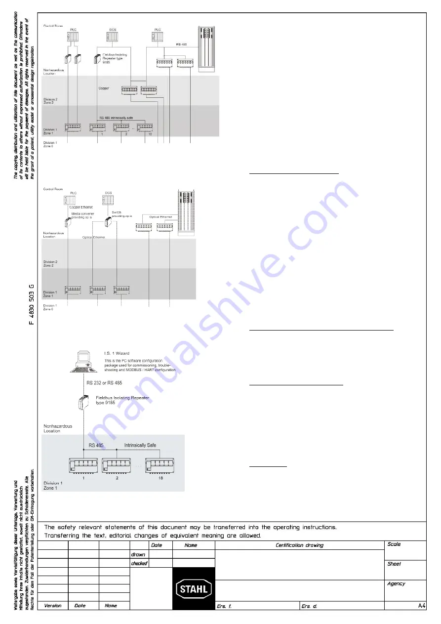
Example for Fieldbus System Topology with Bus Isolators
interfacing Automation control systems with DIV 1 / Zone 1
installation of IS1 resp. IS1+ Remote I/O System
Example for Ethernet System Topology with Isolators
Interfacing Automation control systems with DIV 1 / Zone 1
installation of IS1 resp. IS1+ Remote I/O System
Service Bus with Isolating Repeater interface
The IS1 resp. IS1+ Remote I/O is a DIN rail mounted system designed
to record and output process control signals between hazardous
location transducers, sensors and a nonhazardous location automation
system. It consists of electrical apparatus in a Class I, Division 1 or
Class I, Zone 1 hazardous locations linked by an intrinsically safe field
bus installed per the National Electrical Code, ANSI/NFPA 70 Article
500.
The intrinsically safe field bus circuit is achieved with the use of the
Fieldbus Isolating Repeater type 9185 (copper to copper interface) or
9186 (fiber optic to copper interface). These devices reside in the
nonhazardous location and provide a intrinsically safe field bus circuit
for connection to the IS1 resp. IS1+ Remote I/O System. See example
to the left.
The apparatus located in the Division 1 or Zone 1 hazardous location
are referred to as Remote I/O, and consist of the following major
subsystems.
Notes:
1.
CPU & Power Module, Type 9440
The CPU and Power Module contains a power supply unit for its
own power supply, as well as for the supply to the I/O modules
and the field circuits. The power supply to the I/O modules is
implemented via the BusRail. For the configuration with a
redundant CPU and Power Module the power supply to the I/O
modules is decoupled with diodes. The power supply unit has an
undervoltage monitoring circuit.
The CPU fulfils the function of a gateway between the internal
bus of an IS1 field station and the fieldbus which connects the
field station with the automation system. The gateway is
constructed as a dual processor system. The I/O processor
controls the data exchange with the I/O modules and, when
plugged-in, with the redundant CPU & Power Module. The
communication processor controls the data exchange on the
fieldbus, the redundant fieldbus and on the Service Bus.
The communication with the I/O modules is implemented via the
address and data lines on the BusRail. The interface of the CPU
& Power Module with the internal data bus on the BusRail is
designed with redundancy.
2.
CPU Module Type 9441 and Power Module Type 9444
The IS1 System for Ethernet uses a separate Power Module and
CPU Module pluggen onto an associated Socket instead of the
CPU&Power Supply Type 9440. Except for the external
communication which is achieved via optical fibre interface, the
Power Module and the CPU Module provide similar functions as
the CPU&Power Module type 9440.
3.
Components of Remote I/O System
All I/O Modules are manufactured in a unique DIN rail mount
package which then mount onto the Remote I/O system BusRail.
4.
Refer to pages 4 through 25 for information specific to each
module.
GENERAL NOTES:
1.
Installation should in accordance with Article 504/505 of the
National Electrical Code, ANSI/NFPA 70 and ANSI/ISA
RP12.06.01 resp. with the Canadian Electrical Code, Part I.
2.
Use a general purpose enclosure meeting the requirements of
ANSI/ISA S82 for use in nonhazardous or Class I, Division 1
hazardous (Classified) Locations.
3.
Use an FMRC Approved or NRTL listed Dust-ignitionproof
enclosure appropriate for environment protection in Class II,
Division 1, Groups E, F and G; and Class III, hazardous
(Classified) Locations.
4.
Substitution of components may impair suitability for Zone 1 and /
or Intrinsic Safety.
Содержание IS1
Страница 13: ......


