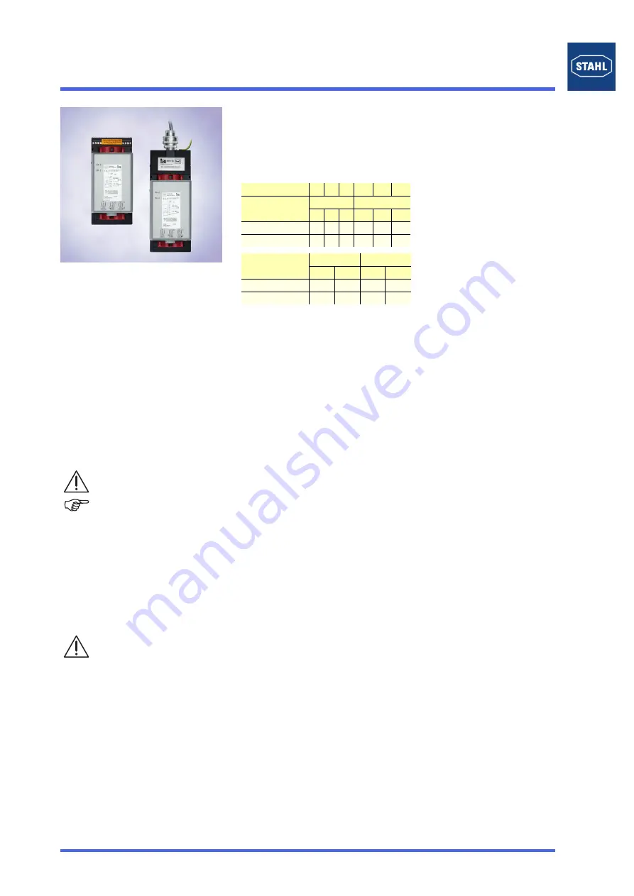
IS1 I/O-Modules
Digital Output Module Relay and Sockets for Installation in Zone 1 / Div. 1 Series 9477/12 / 9490
1
201
-
-
·BA00·III·en·0
201526 / 9477610310
www.stahl-ex.co
P2
perating Instructions for the IS1-System
09895E02
Digital Output Module Relay and Sockets for Installation in Zone 1 / Div. 1 Series 9477/12 / 9490
>
6 or 8 channels: volt-free relay contact, normally open
>
High switching capacity, up to 100 VA
>
Galvanic isolation between outputs and system
>
Connection of the field cables by means of Ex e terminals
or conduit
>
Module can be replaced in operation (hot swap)
General Information
Zone
0
1
2
20 21
22
Class
I
II / III
Zone
0
1
2
20 21
22
Ex interface
X X
Installation in
X X
Class
I
II / III
Division
1
2
1
2
Ex interface
X
X
Installation in
X
X
Manufacturer
R. STAHL Schaltgeräte GmbH
Am Bahnhof 30
74638 Waldenburg, Germany
Telephone:
+49 7942 943-0
Fax:
+49 7942 943-4333
Internet:
www.stahl-ex.com
Service&Support:
Further Information on the Module
Further information on the module you will find
✗
in the automation catalogue (168465 / 00 006 54 78 0) or
✗
on the internet at www.stahl-automatisierung.de
Symbols
Safety Instructions
The most important safety instructions are summarised in this
section. They supplement the corresponding regulations which
the personnel in charge must study. When working in hazardous
areas, safety of the personnel and plant depends on complying
with all relevant safety regulations. Assembly and maintenance
staff working on installations therefore have particular
responsibility.
A precise knowledge of the applicable standards and regulations
is required.
✗
the national safety, accident prevention, assembly and
installation regulations (e.g. IEC/EN 60079-14)
✗
generally recognised technical regulations,
✗
the safety instructions and information of this document,
characteristic values of the type labels and the instruction
plates
✗
the EC Type Examination Certificate (according to ATEX) or
conformity or partial certificate (after previous approval) and
special conditions contained in it
✗
that any damage may render explosion protection null and
void.
✗
that the Digital Output Module of Type 9477/12-0.-12 is
certified for application in hazardous areas of Zone 1/
Division 1, Zone 2/Division 2 or in the safe area.
✗
that, when used in hazardous areas, the module must be
fitted into an enclosure which is certified according to
increased safety requirements (e.g. R. STAHL Type 8126).
✗
that work at the Ex e terminal is only permitted if it is
de-energised.
✗
that only non intrinsically-safe circuits can be connected to
the Ex e terminals.
✗
that the max. values for current, voltage and power
(see Technical Data) must be observed. The switching
current of the contacts must be limited to 2 A (e.g. fuse or
current limitation).
✗
that after connection of the field devices to the Ex e terminal
ingress protection IP30 must be ensured.
✗
A corresponding instruction plate must be placed on the
enclosure.
✗
Conductors with a small cross-section must be connected
with insulated end covering sleeves.
✗
At the socket 9490/11-34 unused connection terminals must
be protected against accidental contact (e.g. by means of a
special cover or an appropriate sealing of cable entries).
Use the component in accordance with its designated use and for
its intended purpose only (see chapter "Function/
Characteristics"). Incorrect and impermissible use or non-
compliance with this document invalidates our warranty
provision.
No modifications or alterations to the components, impairing their
explosion protection, are permitted.
The components are to be fitted only if they are undamaged and
clean.
Conformity to Standards
The components comply with the following standards and
directive:
✗
Directive 94/9/EC
✗
IEC 60079-0: 2004; IEC 60079-1: 2007-04; IEC 60079-7:
2006-07; IEC 60079-11: 2006
Function/Characteristics
Each output is an individual volt-free contact per channel.
They are operated as contact makers (normally open).
Logic "0" = contact open; logic "1" = contact closed.
The connection terminals of the module are Ex e terminals.
Connect only non intrinsically safe circuits.
Communication with the CPU & Power Module is achieved using
the address and data circuits of the BusRail, which also contains
the circuits for the power supply to the module.
The interface of the Digital Output Module with the internal data
bus of the BusRail is designed with redundancy.
Attention!
This symbol marks notes whose non-observance will
endanger your health or functioning of the device.
Note
This symbol marks important additional information,
tips and recommendations.
As the user, please note:
Содержание IS1
Страница 13: ......


