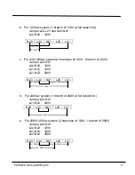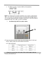
Form No. 003-2282 Rev G
19
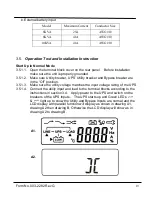
b. External battery input
3.5.
Operation Test and Installation Instruction
Start Up in Normal Mode
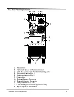
3.5.1.1. Open the terminal block cover on the rear panel. Before installation
make sure the unit is properly grounded.
3.5.1.2.
Make sure Utility breaker, UPS’ Utility breaker and Bypass breaker are
in the
“Off” position.
3.5.1.3. Make sure the utility voltage matches the input voltage rating of the UPS.
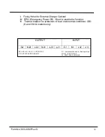
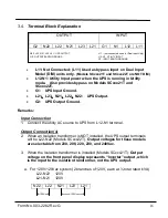
3.5.1.4. Connect the utility input and load to the terminal blocks according to the
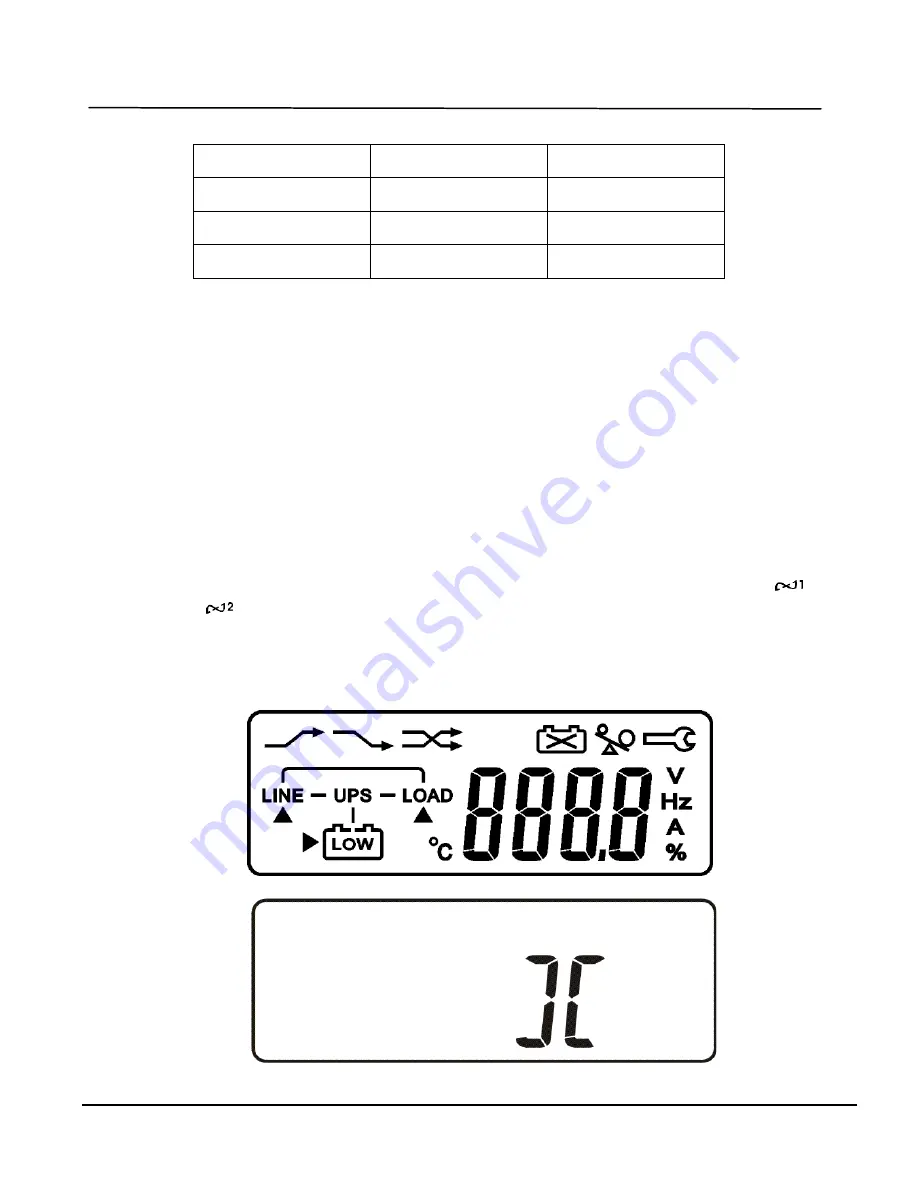
instructions in section 3.4. Apply power to the UPS and switch on the
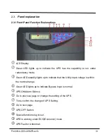
breakers of the UPS Inputs. The UPS starts up and Green LEDs
&
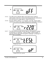
light up to show the Utility and Bypass Inputs are normal and the
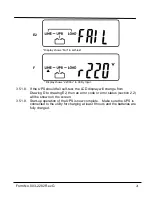
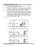
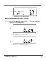
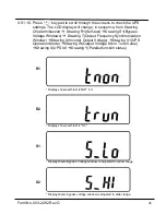
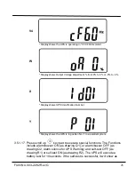
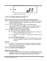
LCD display with parallel function will display as shown in drawing A1,
drawing A2 then drawing B. Otherwise the LCD display will show as in
drawing A2 to drawing B.
A1.
A2.
Model
Maximum Current
Conductor Size
6KVA
25A
AWG #10
8KVA
41A
AWG #10
10KVA
41A
AWG #10

