16
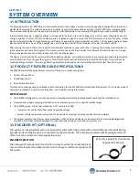
5.1 OVERVIEW
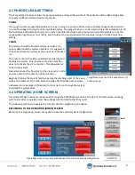
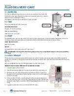
The fluid tank features a level sensor to monitor and produce a fault when the
fluid falls to a low level. The tank also features a 3
-
way ball valve at its outlet for
fluid draining and cleaning purposes.
Fluid Delivery Cart Dimensions:
40.500”
x
31.263”
x
54.502”
5.2 TANK
Tank is mounted using 4
3/8”
-
16
screws
TANK SPECIFICATIONS:
Capacity: 15 Gal, Cone Bottom
Material: Polyethylene
Dimensions:
16”
x
16”
x
24”
5.3 PUMP
The ES2500 pump comes standard with one pump to power fluid delivery to the Electrostatic Manifold(s). It has a mo-
tor driven, progressive cavity pump, with speed adjusted by the ES2500 control panel for desired flow.
PUMP SPECIFICATIONS:
Max flow: 10 GPH
SET
-
UP
Pump gets fed from the tank with a
3/4”
Tygon hose.
ATTENTION: Viscosity of the fluid being sprayed may have a significant impact on the pump specifica-
tions.
5.4 LEVEL SENSOR
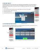
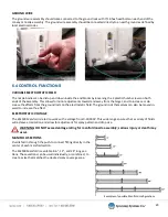
The level sensor sends a signal when the tank gets low to let the control panel know when to shut off the system to
prevent the pump from running dry and becoming damaged. The level sensor gets wired into the ES2500 control panel
by cable.
See CH1 Configuration section for setting parameters in the control panel.
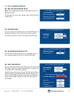
CONNECTING THE LEVEL SENSOR TO THE CONTROL PANEL
1.
Connect power to the controller.
2.
Plug the level sensor cable into the sensor mounted to the main tank unit.
3. An NPT thread push tube fitting needs to be added to the air inlet port on
the bottom of the controller provided by the customer. Air must be supplied
to the air inlet port.
4. The auto
-
refill controller unit will supply air to the pneumatic valve when
the main tank level is low. In that case, the yellow light on the controller will
illuminate indicating the automatic refill has been triggered and is currently
filling.
5. Supply air to the inlet on the control box (0
-
100 PSI max.)
SECTION 5
FLUID DELIVERY CART
Strainer
Fluid Tank
Pump/Motor


