background image

13


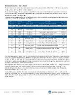
ALARM HISTORY SCREEN 


The Alarm History screen allows operators to view any ongoing or past alarms. This screen will log the time that an 
alarm occurs, as well as the specific alarm fault code.


ALARM SETTINGS 


Alarm settings allows operators to adjust the parameters for system alarms. Most alarms have tolerance times that 
are user

-

controlled settings. The tolerance time determines how long a certain fault can occur before triggering an 

alarm. Operators can also disable certain alarms if desired. 


Stack Light 


The Stack Light serves as an easy visual indication for the current system status of the ES2500. The Stack Light fea-
tures three possible notification lights: green, amber, and red. The green and red lights can appear as either a solid or 
flashing illumination. 


• 

Green: 

When the stack light is green, it represents normal system conditions. 


-

 Solid green

-

 the system is ready for operation 


-

 Flashing green

-

 occurs during system operation. 


• 

Amber: 

When the stack light is displaying an amber light, it represents that the system is not ready for operation. 


• 

Red (Warning): 

The stack light appears red when 

there is a system fault and the Emergency stop 
button is deployed. 


-

 Solid red

-

 a standard system fault


-

 Flashing red

-

 a critical system fault. 


Содержание AutoJet ES2500

Страница 1: ...AutoJet ES2500 Electrostatic Manifold System OWNER S MANUAL MI102012 000 spray com...

Страница 2: ...9 4 4 Operating Home Screen 9 4 5 Recipe Setup 10 4 6 System Configuration 10 4 7 CH1 Configuration 11 4 8 Motor Driver Information 12 4 9 Alarm Settings 12 4 10 Monitor IO Settings 14 4 11 Help Sett...

Страница 3: ...damage the system CAUTION Product process or environment can be damaged or be in danger if the instructions are not followed correctly ATTENTION Supplementary information for the user that draws atten...

Страница 4: ...e can penetrate skin and cause severe injury ATTENTION Always remember to carefully read the chemical manufacturer s labels follow SDS and all directions WARNING OF SHOCK HAZARD To reduce the risk of...

Страница 5: ...et surface The average final drop diameter produced by the Electrostatic Manifold is less than 10 microns 3 2 PRODUCT FEATURES AND SPECIFICATIONS The ES2500 Electrostatic Spray System consists of thre...

Страница 6: ...tio D1 D2 WHEEL AND PIVOT MOUNTED ENCODER Calculating the calibration constant K Factor pulses ft K PPR Wheel CIR ft SPECIFICATIONS Resolution PPR 1024 Output 5 26V push pull Input 5 26V Bore 5 8 holl...

Страница 7: ...uration settings PANEL POWER REQUIREMENTS Voltage 120VAC 3Ph Frequency 60Hz Current 20A max ELECTROSTATIC PANEL FEATURES 10 HMI Touch Screen display Customizable spray parameters Washdown rated Three...

Страница 8: ...when the motor is off and will be green while the motor is running Purge Clean This button brings up the system Purge Clean settings See the Purge Clean section for more information ES2500 Menu Whenev...

Страница 9: ...ilized when cleaning and flushing the system This is because the clean function does not activate the HV connection This allows water to flush the system Operators can set the flow rate for the clean...

Страница 10: ...individual recipe allows you to Create a name Enter the flowrate setpoint in gallons per hour GPH or based on mL per Sq Ft line speed Enter the Electrostatic voltage setpoint in kV Set the pump primin...

Страница 11: ...CH1 HV AMPERAGE FEEDBACK SETUP This screen allows the operator to set an amperage alarm if the amperage exceeds this amount the system will fault CH1 LEVEL SENSOR SETUP Relying on the input data from...

Страница 12: ...eful when troubleshooting the motor 4 9 ALARM SETTINGS The ES2500 system notifies operators of active and ongoing alarms at the top of the HMI screen and via stack light illu mination The Active Alarm...

Страница 13: ...tack Light serves as an easy visual indication for the current system status of the ES2500 The Stack Light fea tures three possible notification lights green amber and red The green and red lights can...

Страница 14: ...en below This screen provides live readings of both the analog and digital aspects of the PLC This screen can pro vide useful information when troubleshooting system components PLUGIN RELAY OUTPUT Thi...

Страница 15: ...ETTING Selecting Help from the navigation menu will bring up a screen that displays system information access the HMI OS Screen Map and change password profiles SCREEN MAP The Screen Map displays all...

Страница 16: ...ions 5 4 LEVEL SENSOR The level sensor sends a signal when the tank gets low to let the control panel know when to shut off the system to prevent the pump from running dry and becoming damaged The lev...

Страница 17: ...e tank will decrease Once the fluid reaches 250 mm from the bottom of the probe 63 full 100 250 10 380 63 Auto Refill will turn on As the fluid level rises and reaches 390 mm from the bottom of the pr...

Страница 18: ...the operator to be able to view the Electrostatic Manifold while at the control panel This will allow for easier adjustments and fine tuning of the electrostatic spray as the operator will be able to...

Страница 19: ...erfere with the electrostatic fields and skew the spray or potentially trip the AccuJet Electrostatic Controller All fluid must be run through a filter capable of removing 90 micron particulates HIGH...

Страница 20: ...rods on the electrostatic field The ground rods themselves can also be moved in ward to increase the effect ELECTROSTATIC VOLTAGE The ES2500 Manifold is rated to work with a voltage from 0 30 000V Thi...

Страница 21: ...connections are properly connected and secure 2 Ensure that the manifold is plumbed and positioned properly above the target 3 Verify that the manifold grounding wires are properly connected Ensure th...

Страница 22: ...DISASSEMBLY WARNING High Voltage Make sure that power has been disconnected to high voltage line before any attempt at disassembly STEP 1 The Manifold nozzles can be removed from the end mounts so the...

Страница 23: ...de should fall out Take note of how the electrode fits inside the bushing STEP 4 Remove the electrode and its gasket Then the through hole bushing should fall out STEP 5 Remove screws from underside o...

Страница 24: ...24 6 8 Electrostatic Manifold Diagram...

Страница 25: ...control panel Check HV cable connection between the system control panel and the manifold Verify trigger signal Check manifold for clogging 3 Air in liquid line poor pump performance Check for leaks C...

Страница 26: ...er pump adjustment Adjustment pump flow by changing the setting in the recipe Damaged or leaking lubricant lines Inspect identify and replace lines Clogged or leaking pump Clean or replace pump Clogge...

Страница 27: ...RM Problems with motor wiring Motor torque speed out of range Review and replace cables if dam aged Check operating conditions and settings specifically max flow Pump servicing may be required System...

Страница 28: ...ve companies Warranty is one 1 year on non wear parts from ship date Wear items are covered for manufacturing defect only for a period of one 1 year Wear items include but may not be limited to Liquid...

Отзывы: