

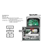
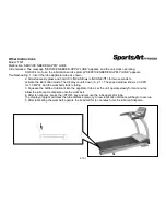
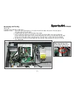
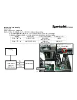

Inspecting and Testing
Model: T621
Name: Incline motor voltage test
Method: 1. Set the voltmeter to the 300 VAC or higher voltage setting.
2.
Press INCLINE<▲>/<▼> keys. Incline indicator LEDs on the drive board light.
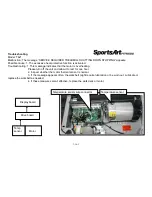
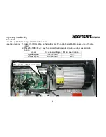
3. Measure voltage output to the incline motor. Normal readings are shown below.
Display
Drive board
Incline motor cables
Incline operates
Press <▲> key
Led9 UP lights
white-black
110V or 220V
upward
Press <▼> key
Led7 DOWN lights
white-red
110V or 220V
downward
4-7-1
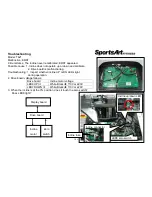
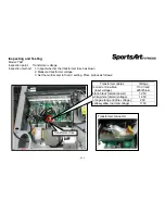
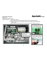
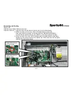
Display
Drive board
LED9 UP
LED7 down
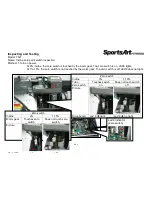
Incline motor
Red
Black
White
Incline motor
connector
LED9 incline-up
Indicator
LED7 incline-down
Indicator
Incline fuse
Содержание T621
Страница 1: ...T621 Repair Manual Electronics ...
Страница 4: ...1 1 Product Picture T621 1 1 1 ...
Страница 5: ...1 2 Display T621 1 2 1 ...
Страница 6: ...1 3 Component Placement T621 Display 1 3 1 Telemetry heart rate receiver board Display board ...
Страница 7: ...1 3 Component Placement T621 Display 1 3 2 HTR board Bridge board Soft keys Safety key board ...
Страница 11: ...1 5 Connections T621 Bridge Board 1 5 2 To safety key board To HTR board To display ...
Страница 13: ...1 6 Indicator LEDs T621 Display Board 1 6 1 HR indicator Power indicator Lit indicates display has power ...