
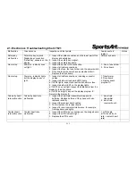


Soft key
malfunction
(display)
Press soft key, display no rebound,
1. Replace the display soft key.
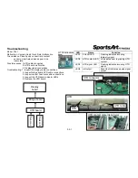
Soft key
(display)
Soft key
malfunction
Key does not operate,
or operates continually.
1. Inspect the bridge board soft key connection.
2. Replace the soft key.
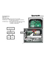
Soft key
ERR 1
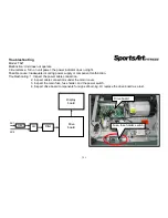
Motor does not rotate, ERR1
appears.
1. There is no power to the motor; the motor
cannot operate.
2. Inspect the motor brushes.
3. Measure voltage from the drive board
to the motor. If there is no voltage, replace the
drive board. If there is voltage, inspect the
following:
a. transformer voltage
b. whether the EMG indicator lights
c. whether IGBTs have an electrical
short. If so, replace the drive board.
4. Inspect the motor brushes and the
commutator.
1. Drive board
2. Motor brushes,
commutator
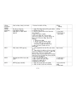
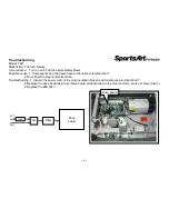
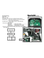
ERR 1
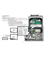
Motor rotate, ERR1 appears,
1. The program did not detect the optic sensor
signal.
2. Inspect the CLK indicator on the drive board.
If the CLK indicator is not lit, clean or replace the
speed sensor. If the CLK indicator lights
normally, inspect the data cable from the display
to the drive board. Re-install the display program
IC. Re-install the display IC.
Speed sensor
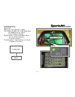
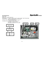
ERR 3
Display speed differs from actual
speed.
1. Inspect the KPH/MPH setting.
2. Inspect teeth on the optic wheel.
3. Replace the speed sensor.
4. Replace the drive board.
1. Speed sensor
2. Drive board
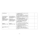
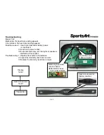
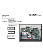
ERR 7
ERR7 appears at startup.
1. Inspect the incline cable connections.
2. Inspect whether incline has calibrated.
1. Zero calibration
switch
2. Drive board
2-1-2
Содержание T621
Страница 1: ...T621 Repair Manual Electronics ...
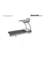
Страница 4: ...1 1 Product Picture T621 1 1 1 ...
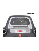
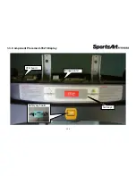
Страница 5: ...1 2 Display T621 1 2 1 ...
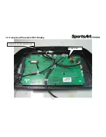
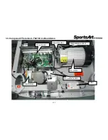
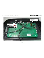
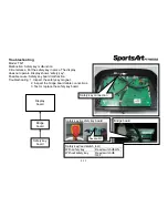
Страница 6: ...1 3 Component Placement T621 Display 1 3 1 Telemetry heart rate receiver board Display board ...
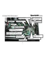
Страница 7: ...1 3 Component Placement T621 Display 1 3 2 HTR board Bridge board Soft keys Safety key board ...
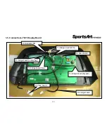
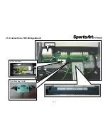
Страница 11: ...1 5 Connections T621 Bridge Board 1 5 2 To safety key board To HTR board To display ...
Страница 13: ...1 6 Indicator LEDs T621 Display Board 1 6 1 HR indicator Power indicator Lit indicates display has power ...