ST/STR/STA MANUAL
20
118107-001 REV J
5.7 Parallel Option Units
(Multiple Chassis Systems
– ST
only)
Physically install the units in a cabinet or stack them one
on top the other, typically the Master units is located at
the top to ease access to the local controls on the full
featured front panel. Cabling up the system is similar
regardless of the numbers of Slave chassis. The following
items will be required to connect up each parallel option
unit:
Control Jumper Cable (gray cable, 15 pin D connecters on
each end)
Ground Jumper Cable (green/yellow cable, ring lugs on
each end)
High Voltage Jumper Cable (black cable, HV connecter
on each end)
Terminator Plug (black plastic clam shell, 15 pin D
connecter)
One cable of each type is required for each Slave chassis;
only one terminator plug is required for each system. The
connections are as follows; repeat as needed for additional
Slave Chassis:
Control Jumper Cable
– Connect one side to JB3 of the
Master chassis, connect the other side to JB4 of the Slave
Chassis.
Ground Jumper Cable
– Connect one side to E1 ground
stud on the Master chassis, connect the other side to E1
ground stud of the Slave chassis. ***Connect the
customer provided “System Ground Cable” and the
customer provided “Load Return Cable” to the E1 ground
stud on the back of the Master Chassis. Please see Typical
Operating Setup ST figure for required ground
connections***
High Voltage Jumper Cable
– Connect one side to J1 of
the Master chassis; connect the other side to J1 of the
Slave Chassis. Connect the terminated side of the High
voltage output cable to J2 of the Slave chassis; connect
the unterminated side to the load as applicable.
Terminator Plug
– Plug the Terminator Plug into JB3 of
the Slave Chassis.
The instructions above are for a two chassis Master/Slave
unit, but these instructions can be used for systems with
any number of Slave units keeping these two points in
mind:
●The High Voltage Output Cable always exists from the
“last” Slave unit
●The Terminator Plug is always connected to the JB3
connecter of the “last” Slave unit.
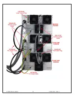
See the annotated photograph of the wiring connections
for a 3 chassis system (Master/Slave1/Slave2) that
follows these instructions.
Cooling Note:
For proper cooling, and to maximize product life span, a
minimum of 1U (1.75”) rack space should be provided
above and below each chassis, and between chassis of
multi-chassis systems. This will allow air circulation, and
also reduce heating effects on other equipment in the
cabinet.


