


118142-001 Rev B
Page 9 of 104
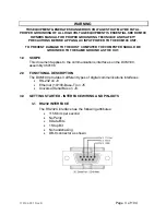
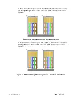
Figure 7 – Block Diagram of USB Cable Utilizing Ferrites
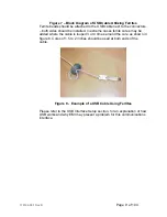
Ferrite beads should be attached to the USB cable next to the connectors
– both sides should be installed. In extreme cases ferrite cores may be
added where the cable is looped 3 or 4 times around the core as shown in
figure 8. Cores of 1.5 to 2 inches should be used at both ends of the
cable.
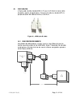
Figure 8 - Example of a USB Cable Using Ferrites
Please refer to the USB Interface Setup section, for an explanation of how
USB works and why EMI may present a problem for this communications
interface.
Содержание DXM100 Series
Страница 11: ...DXM100 MANUAL 5 118147 001 Rev D Figure 2 1 Unit Dimensions ...
Страница 16: ...DXM100 MANUAL 10 118147 001 Rev D Figure 3 3 Local Programming Via External Voltage Source ...
Страница 17: ...DXM100 MANUAL 11 118147 001 Rev D Figure 3 4 Remote Monitoring ...
Страница 18: ...DXM100 MANUAL 12 118147 001 Rev D RELAY Figure 3 5 Enable Interlock Logic Control ...
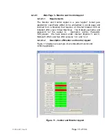
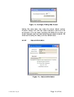
Страница 37: ...118142 001 Rev B Page 13 of 104 Figure 9 Web Page 1 Contact Information ...


