background image

SPECTRA PRECISION FOCUS 2 SERIES TOTAL STATION USER GUIDE

6 – 

Menu Key

114

CO (comment) records

A CO record is a comment added to the job from the system.

For example, when the Stn-Z is changed using the Z-Coord 
function, or the horizontal angle is reset using the BSCheck 
function, the system writes a comment record. This screen 
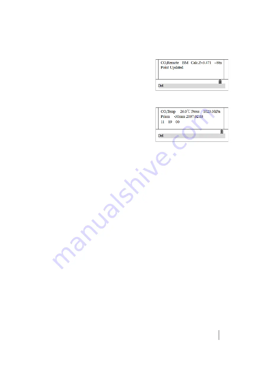
shows an example of a comment in the Z-Coord function.

When a Stn-XYZ is input by Base-XYZ function, the recorded 
station appears as a comment record.

This screen shows a record of temperature, pressure, and 
prism constant that is saved when the station setup is 
completed. 

Deleting raw records

1. In the 

RAW

 screen (or in the data screen that appears 

when you press 

[REC/ENT]

), press 

[^]

 or 

[v]

 to highlight the record to be deleted. 

2. Press the 

DEL

 softkey.

A confirmation screen appears.

3. To delete the selected record, press 

[REC/ENT]

 or the 

OK

 softkey. (Otherwise, press the 

CE


softkey.)

The system returns to the 

RAW

 data screen.

Editing raw records

1. In the 

RAW

 screen (or in the data screen that appears when you press 

[REC/ENT]

), press 

[^]

 or 

[v]

 to 

highlight the record that you want to edit. 

2. Press the 

Edit

 softkey.

3. Enter the new data manually or select data using the 

List

 or 

Stac

 softkey and then press 

[REC/ENT]

4. To rewrite the data, press 

[REC/ENT]

 or the 

OK

 softkey. (Otherwise, press the 

CE

 softkey.)

The system executes the selected operation and returns to the 

RAW

 screen.

Содержание FOCUS 2 Series

Страница 1: ...Version 1 0 Revision C March 2015 User Guide Spectra Precision FOCUS 2 Series Total Station...

Страница 2: ...stered in the United States and in other countries The Bluetooth word mark and logos are owned by the Bluetooth SIG Inc and any use of such marks by Spectra Precision is under license All other tradem...

Страница 3: ...ry C CAUTION Cautions alert you to situations that could cause injury or property damage Always read and follow the instructions carefully Warnings Before using the instrument read the following warni...

Страница 4: ...d or dusty places in direct sunlight or near heat sources Do not recharge the battery pack when it is wet If you do you may receive electric shocks or burns or the battery pack may overheat or catch f...

Страница 5: ...the clamp screw on the tripod If the clamp screw is not securely fastened the instrument may fall off the tripod causing personal injury or instrument damage C CAUTION Securely fasten the tribrach cla...

Страница 6: ...y damage To prevent injury or damage If you come in contact with the electrolyte wash the exposed area with soap and water If the electrolyte make contacts with your eye immediately rinse the eye with...

Страница 7: ...ook directly with or without an optical instrument into the beam C WARNING The laser beam should be terminated at the end of its useful beam path and should in all cases be terminated if the hazardous...

Страница 8: ...ngth 620 to 690 nm Output power Pulse Pp 8 75 mW Po 4 75 mW 1 2 nsec 400 MHz 1 6 nsec 320 MHz Distance meter in Prism mode Wave length 620 to 690 nm Output power Pulse Pp 0 037 mW Po 0 02 mW 1 2 nsec...

Страница 9: ...battery pack 25 Detaching the battery pack 25 Inserting the battery pack 25 Battery power remaining indicator 26 Setting up the tripod 26 Centering 27 Centering using the optical plummet 27 Centering...

Страница 10: ...4 Multiple point resection 58 Quick station 61 Height transfer determining station elevation 62 Checking and resetting the backsight direction 63 Stakeout key 64 Stakeout by angle and distance 64 Coor...

Страница 11: ...settings 128 DSP key settings 128 USR key settings 129 S O key settings 129 DAT key settings 130 Date and time 131 Format 131 Information 132 7 Checking and Adjustment 133 Adjusting the electronic le...

Страница 12: ...Vertical curve 149 B Calculate Road Alignment 150 Road alignment elements 151 Enter the alignment data 151 Calculating road alignment elements 153 Length of transition curve 153 Deflection angle 154...

Страница 13: ...strument Accessories Display Keypad Softkeys Symbols Illumination and sound Auto power off Thank you for purchasing this product Before you operate a FOCUS 2 Series total station read this manual care...

Страница 14: ...of the FOCUS 2 Series total station Figure 1 1 FOCUS 2 Series total station Face 1 Telescope Diopter ring Telescope Carrying handle Optical sight Reticle plate cover Leveling screw Display Telescope f...

Страница 15: ...ollowing items are supplied with the instrument Item Quantity Carrying case 1 Total station main body 1 Battery 2 Charger and adapter cable 1 Plumb bob 1 Adjusting pin 2 Fur brush 1 Screw driver 1 Hex...

Страница 16: ...STATION USER GUIDE 1 Introduction 16 Display Confirm the battery power shown on the display Replace it with another charged battery or change it when battery level is low See Battery power remaining...

Страница 17: ...nation ON OFF Displays the Function menu Changes the mode of input alphabetic numeric launches quick code mode in the Basic Measurement screen Accepts the input or records the data In the Basic Measur...

Страница 18: ...ts number 7 and letters A B and C Displays the Stakeout menu press it for 1 second to display the settings for stakeout inputs number 8 and letters D E and F Displays the Offset Point Measurement menu...

Страница 19: ...scription Please select via left right key To display each screen via up down key Indicates that several pages are selectable Press to turn the page F1 F2 Indicates that the telescope alidade is on Fa...

Страница 20: ...item is selected the function corresponding to the key can be launched ON OFF by pressing the corresponding number Symbol Description HA Horizontal angle VA Vertical angle SD Slope distance AZ Azimuth...

Страница 21: ...sound on and off Sound ON Sound OFF 4 Press 3 or to move to the contrast icon Press 3 continuously to adjust the contrast level 5 Press 4 or to move to the laser plummet icon Press 4 to turn on or off...

Страница 22: ...ng and packing the instrument Charging the battery pack Detaching and reattaching the battery pack Battery power remaining indicator Setting up the tripod Centering Leveling Sighting Setting the measu...

Страница 23: ...losion or fire and can result in personal injury and or property damage To prevent injury or damage Do not use or charge the battery if it appears to be damaged Signs of damage include but are not lim...

Страница 24: ...d with other chargers C WARNING Do not cover the battery charger and AC adapter while the battery pack is being recharged The charger must be able to dissipate heat adequately Coverings such as blanke...

Страница 25: ...emperatures above 40 C to 45 C If the charge indicator s does not light after connecting the battery and charger the battery or the charger may be damaged Please contact your authorized service center...

Страница 26: ...hould always be checked prior to outdoor operation When the measurement mode is changed the battery power does not immediately update The battery power indicating system shows the general status but n...

Страница 27: ...While looking through the optical plummet align the center mark of the reticle with the station point To do this turn the leveling screws until the center mark of the reticle is directly over the imag...

Страница 28: ...ering using a plumb bob 1 Set up the instrument on the tripod See Setting up the tripod page 26 2 Hang the plumb line on the hook of the tripod mounting screw 3 Adjust the length of the plumb line so...

Страница 29: ...leveled manually 2 Press MSR2 to shift the compensation mode to dual axis compensation 3 After leveling press ESC to return to previous status 4 To close automatic compensation press OFF When the ins...

Страница 30: ...necting leveling screws c and d and then bring the bubble to the center of the plate vial by turning the leveling screws c and d b Rotate the instrument 90 around its vertical axis and turn the remain...

Страница 31: ...ile sighting through the eyepiece rotate the diopter ring until the reticle crosshairs are brought into sharp clear focus 2 Elimination of parallax a Aim the telescope at the target b Rotate the focus...

Страница 32: ...t the prism when the laser pointer is on Measurement with a prism Do not use a prism that is damaged dirty scratched or chipped As the FOCUS 2 Series total station is extremely sensitive multiple refl...

Страница 33: ...le prism and triple prisms which can be mounted in a tribrach onto a tripod or mounted onto a prism pole Reflector systems can be self configured by users according to the job Mounting and dismounting...

Страница 34: ...Insert the three anchor jaws into holes in the tribrach and line up the directing stub with the directing slot Turn the locking knob about 180 clockwise and tighten the locking screw with a screwdrive...

Страница 35: ...nt values most constant mechanical errors can be cancelled out Some errors such as vertical axis error cannot be cancelled out by averaging Face 1 and Face 2 measurements When rotating the telescope t...

Страница 36: ...3 SPECTRA PRECISION FOCUS 2 SERIES TOTAL STATION USER GUIDE 36 C H A P T E R Getting Started 3 In this chapter Input modes Entering a point name or number...

Страница 37: ...splays the next letter for that key in the cursor The methods for Code CD input are enter manually select from a list and select from a stack The operational methods are the same as that of entering a...

Страница 38: ...Enter PtID in the PT field and then press REC ENT The system searches for the point ID in internal memory If this Point ID exists its coordinate are displayed 2 Press REC ENT to return to the screen...

Страница 39: ...uired Press REC ENT to confirm 4 If the input PtID exists in internal memory its coordinate will be displayed on the screen Press REC ENT to return 5 If the input PtID does not exist enter a coordinat...

Страница 40: ...ot exist enter a coordinate and then press REC ENT to move the cursor to the code CD item Enter the code Press REC ENT to save and quit Entering a point using a temporary coordinate In some cases when...

Страница 41: ...rs 2 Press MSR1 or MSR2 to start a measurement To change the height of the target press the HT softkey After measuring the point recording screen appears 3 Enter the point ID and CD and press REC ENT...

Страница 42: ...ng HOT key Starting a survey Angle measurement Quick codes After correctly setting up and starting the instrument it is immediately ready to take measurements All shown displays are for illustrative p...

Страница 43: ...be changed and then press or to change the options 3 After setting press REC ENT to save the setting and return to the last screen TGT Prism reflector sheet and non prism Const Input prism constant d...

Страница 44: ...HT stack stores the last 20 HT values entered 3 Press REC ENT to return to the Basic Measurement screen Setting the temperature and pressure Atmospheric correction The speed of light in the air is ex...

Страница 45: ...he program calculates the atmospheric correction value and returns to the normal measurement screen The atmospheric correction value is calculated according to the input temperature and pressure value...

Страница 46: ...t set in the list and then press the Edit softkey When a target set is selected the Type and Const values are copied to both MSR1 and MSR2 settings If you have specified a value for HT this value is a...

Страница 47: ...y time on any observation screen Each note can be up to 50 characters The note is stored as a CD record in the raw data To enter a field note 1 From the HOT key menu press 4 or press v and REC ENT to...

Страница 48: ...king a measurement the prism constant is displayed in the distance field The measurement results are displayed in four screens including all normal measurement data such as angle distance and coordina...

Страница 49: ...EC ENT to select Input The HA Input screen appears 2 Enter the horizontal angle value and then press REC ENT For example to enter 159 46 25 type 159 4625 The software returns to the Basic Measurement...

Страница 50: ...press ESC 4 Press REC ENT to save the horizontal angles and return to the initial repeat angle measurement screen 5 Repeat Step 3 through Step 4 as many times as needed When enough horizontal angle r...

Страница 51: ...rrent vertical circle reading If the vertical circle is on F2 the message Turn to F1 appears If the vertical circle is on F1 the message Turn to F2 appears 4 Rotate the alidade and use the horizontal...

Страница 52: ...code in the code list 10 tenth code in the code list For more about editing quick codes see Adding a code page 120 You can also use the included Data Transfer software to create and upload codes See C...

Страница 53: ...5 SPECTRA PRECISION FOCUS 2 SERIES TOTAL STATION USER GUIDE 53 C H A P T E R Applications 5 In this chapter Station key Stakeout key Measuring offsets Program Key COD key DAT key USR 1 USR2 keys...

Страница 54: ...ess 1 to select Known The Input STN screen appears 2 Enter a point name or number in the ST field and press REC ENT 3 Enter the HI Height of instrument and press REC ENT To re enter the known PtID pre...

Страница 55: ...enter the height of target in the HT field 2 Sight the BS on Face 1 F1 and press MSR1 or MSR2 to record a full shot with HA VA SD value If the vertical circle is on Face 2 a message Turn to F1 appears...

Страница 56: ...muth calculated by coordinates Note Press v or DSP to switch to the QA screen dHD and dVD values which indicate the difference between the measured distance and the distance calculated from the known...

Страница 57: ...display the coordinate of this point and enter into the function of sighting the backsight by entering coordinates 3 If only the azimuth needs to be entered when the cursor is in the BS field press RE...

Страница 58: ...ion using angle distance measurements to known points A maximum of 10 points can be used in a resection Measurements can be distance and angle or angle only Calculation starts automatically when enoug...

Страница 59: ...F1 appears If this happens rotate the telescope and alidade and sight the BS point in Face 1 5 The measurement result appears Press REC ENT To measure the backsight point on F2 press the F2 softkey R...

Страница 60: ...first observed point To change the BS press the Vary softkey a Press v or to select the BS point that you want to use and then press REC ENT 13 The Input STN menu screen appears Press REC ENT to recor...

Страница 61: ...en two known points ST and BS select Station Setup Known 1 From the Stn Setup menu press 3 or press v and REC ENT to select QuickStn The QuickStn screen appears 2 Enter the ST point name and then pres...

Страница 62: ...target prism and then press REC ENT 4 Sight the center of the prism and then press MSR1 or MSR2 to measure If the vertical circle is on Face 2 a message Turn to F1 appears If this happens rotate the...

Страница 63: ...5 or press v and REC ENT to select BS Check The BS Check screen appears 2 Sight the BS point and press the Redo softkey or REC ENT to reset the horizontal angle to the HA set in the last station setup...

Страница 64: ...s displays the ST HI and BS set in the last operation Press the OK softkey to confirm or press the Abrt softkey to quit the program After the program records the STN data the screen returns to the SO...

Страница 65: ...on the stakeout point The fifth line shows the Cut or Fill data 8 After staking out press REC ENT to record the stakeout point PT defaults to the last recorded PT 1 input code CD if necessary Press R...

Страница 66: ...easurement of target prism Press MSR1 or MSR2 for 1 second to change the measure mode Press or v to move to the item to change press or to change TGT Prism non prism reflector sheet Const Enter the pr...

Страница 67: ...press the Fr To softkey in the PT field as shown Enter the start point Fr and the end point To The last digit of the point name must be a number If existing points are found between Fr and To a point...

Страница 68: ...L and IN OUT display 0 m it indicates the prism is on the stakeout point The fifth line shows the Cut Fill data Note Once a measurement is taken the Cut Fill value and Z coordinate are updated as the...

Страница 69: ...n guides the stake out of the points one by one For example if a measurement is taken to the end point at 100 m from the instrument and the span total is set to 2 the following four points are calcula...

Страница 70: ...s to the last recorded PT 1 and a CD code may also be entered if required 7 After recording the point the display returns to the SO screen Press the Prev Next softkeys or use or v to stakeout other di...

Страница 71: ...ut point The fifth line shows the Cut Fill data 9 After staking out press REC ENT to record the stakeout point PT default to the last recorded PT 1 and a CD code can be entered if required 10 After re...

Страница 72: ...the STN softkey to enter the Stn Setup menu and select one method to set the station Press the OK softkey to confirm or press the Abrt softkey to quit the program After the program records the STN dat...

Страница 73: ...ach result screen 3 To take the angle offset rotate the alidade and telescope The measured distance HD remains unchanged 4 To record the offset point press REC ENT or the OK softkey alternatively pres...

Страница 74: ...and the second prism blank 4 If a P1 P2 distance is entered the QA screen appears Compare the entered value and the measured distance to check the accuracy of the observation To re enter the distances...

Страница 75: ...Note The calculated point TGT is stored as an SS record Note Measurements to the first and second target P1 and P2 are stored as comment records PT1 and PT2 The last record records the angle measureme...

Страница 76: ...the same wall as the first point measurement Press MSR1 or MSR2 4 Sight the first point on the second wall Press MSR1 or MSR2 5 If the two walls are at right angles press the Calc softkey to calculate...

Страница 77: ...NT or the OK softkey Sight the other edge of the column It also calculates the coordinates of the center point and the radius of the circle 7 In the dialog if the result is satisfactory press the OK s...

Страница 78: ...ne 3 Enter the second point for the reference line 4 Sight the target and press MSR1 or MSR2 After measuring the results display 5 Press REC ENT to record the line Press v or the DSP softkey to switch...

Страница 79: ...t on the tangent line that is to exit the curve Use Rad AZ2 to define the arc Enter the radius and azimuth of its tangent line AZ2 In the radius Rad field enter a positive value for a clockwise curve...

Страница 80: ...between two points There are two methods available MlmRadial A B A C See MlmRadial page 81 Mlm Cont A B B C See Mlm Cont page 82 Sta Horizontal distance from P1 to the measured point along the P1 P2 l...

Страница 81: ...nt and press MSR1 or MSR2 The distance from the station point to the first point is displayed 3 Sight the second point and press MSR1 or MSR2 The distances between the first and second point are displ...

Страница 82: ...MSR1 or MSR2 The distances between the first and third point are displayed 7 Press REC ENT to record the distances between the first and third point 8 Repeat the procedure to calculate and record the...

Страница 83: ...point numbers can be changed 6 After recording the display returns to the Mlm Cont screen Sight the third point and press MSR1 or MSR2 The distances between the second and third point are displayed 7...

Страница 84: ...o select REM The REM screen appears 2 Enter the height of target HT 3 Sight the target point and press MSR1 or MSR2 The measurement results are displayed 4 Loosen the vertical clamp and turn the teles...

Страница 85: ...the second point P2 to define the plane and then press REC ENT Once the plane is defined the calculated Sta and dZ values are updated as the telescope is moved No distance measurement is required The...

Страница 86: ...calculated a and b values are updated as the telescope is moved No distance measurement is required Press v to display other screens as required 5 To record the point press REC ENT on any screen 6 Ent...

Страница 87: ...start chainage and N E coordinate of start point Enter these details and press REC ENT to display the main line input screen The screen displays the current chainage the azimuth angle of the tangent...

Страница 88: ...middle of the road the azimuth angle of the line is calculated according to the previous elements If the user is to change this azimuth angle the new azimuth angle can be entered manually Arc In the D...

Страница 89: ...s the arc radius value rule that is the arc length cannot be negative To define the transition curve 1 In the Define HZ AL screen press Trns The Transition Definition screen appears 2 Enter the radius...

Страница 90: ...nd the next point When spiral factors A1 or A2 are entered a spiral curve with specified length is inserted between the line and arc Note If A1 A2 are entered according to the lengths L1 L2 of the spi...

Страница 91: ...Z AL The Start Pt screen appears showing the start point data 2 Press the Next softkey to find the alignment data to be edited 3 Enter the new data and then press REC ENT 4 The screen displays the mod...

Страница 92: ...alignment consists of a series of intersections including a chainage height and curve length The length of the start point and the end point must be zero Intersections can be entered in any order Aft...

Страница 93: ...t to view and modify other data Receiving vertical alignment data The method of Receiving VT AL data is same as Receiving HZ AL data See Receiving horizontal alignment page 91 Deleting vertical alignm...

Страница 94: ...o the center line and press REC ENT 5 The screen displays detailed data about the chainage Enter the height of the instrument and then press REC ENT 6 Set the backsight point The backsight can also be...

Страница 95: ...nt stake out data Enter the start chainage chainage increment and the horizontal distance between the offset point and center line Height distance is required if cut fill data is to be staked out O S...

Страница 96: ...al angle to the target point R L Right Left Lateral error IN OUT In Out Longitudinal error CUT FIL Cut Fill 10 Move the rodperson to the target position making R L and IN OUT to display 0 m An up arro...

Страница 97: ...data can be entered through left and right slopes In terms of cut fill use positive symbol to input the required slope the software selects an appropriate slope in the list according to the actual pos...

Страница 98: ...me approach Note If the surface crosses through the hinge point the intersection cannot be calculated Note If the cut fill values of the calculated point are zero the cut fill value is not displayed C...

Страница 99: ...1 or USR2 key Whenever a USR key is pressed the function that is predefined is activated directly The following functions can be assigned to the USR keys Input HT BS Check TGT Cogo Offset Program Temp...

Страница 100: ...IES TOTAL STATION USER GUIDE 100 C H A P T E R Menu Key 6 In this chapter Job Coordinate Geometry COGO calculations Settings Data Communication 1 Sec Keys Date and time Format Information To display t...

Страница 101: ...rrent job and returns to the Basic Measurement screen The following symbols are used Creating a new job 1 In the JobMgr screen press the New softkey The Create Job screen appears 2 Enter a job name no...

Страница 102: ...next field press REC ENT To automatically create a new job press REC ENT in the last field HA Deleting a job 1 In the Job list move the cursor to the job to be deleted by pressing the or v key 2 Press...

Страница 103: ...it can be used to record any measured data 1 Highlight the job to be used as a control job by pressing the or v key 2 Press the Ctrl softkey A confirmation screen appears 3 To confirm press REC ENT or...

Страница 104: ...nts exist in the job the coordinates are displayed automatically If the point does not exist in the job a prompt to enter the coordinates in the coordinate input screen appears The point is recorded w...

Страница 105: ...calculates the angle between two lines defined by three points PT1 is the base point Two lines must be defined by P2 and P3 both from P1 1 From the Inverse menu press 2 or press v and REC ENT to sele...

Страница 106: ...ing the AZ Dist function AZ HD 1 From the Cogo menu press 2 or press v and REC ENT to select AZ Dist The AZ Dist menu appears 2 Press 1 or press v and REC ENT to select AZ HD The Input PT screen appea...

Страница 107: ...creen appears 2 Enter the point name P1 and then press REC ENT For the input method see Step 2 of the Inverse PT PT method on page 104 The Input P2 screen appears 3 Enter P2 and then press REC ENT The...

Страница 108: ...th line This is a convenient way to enter Store points Calculate area 1 From the Cogo menu press 3 or press v and REC ENT to select Area The Points screen appears 2 Enter the first point and then pres...

Страница 109: ...ter the horizontal distance along the baseline STA 5 Enter the horizontal distance perpendicular to the line O S Note A negative value in the STA field means the opposite direction along the defined a...

Страница 110: ...his procedure uses the Angle setting as an example 3 To open the Angle menu press 1 4 Press v v to move to items that need to be changed 5 Press to change the settings and then press REC ENT 6 If any...

Страница 111: ...ter USA Feet USA Inch IntlFeet IntlInch Temp C F Press hPa mmHg inHg Record Store DB RAW XYZ RAW XYZ This setting determines whether raw and or coordinate data is stored when recording SS CP or SO rec...

Страница 112: ...or in the Basic Measurement screen F1 and F2 records are Face 1 and Face 2 measurements SS records are sideshots topo shots All shots from the Basic Measurement screen are stored as SS records To vie...

Страница 113: ...w ST point name is assigned in Stn Setup QuickStn the coordinates of the station are recorded as 0 0 0 SO stakeout records This is data recorded in stakeout functions Press DSP to switch between the s...

Страница 114: ...pleted Deleting raw records 1 In the RAW screen or in the data screen that appears when you press REC ENT press or v to highlight the record to be deleted 2 Press the DEL softkey A confirmation screen...

Страница 115: ...ype field and press or to change the selected point type The options are ALL ST SS SO CP CO and MLM Note If a type in the Type field is selected a value in the CD field does not have to be entered Pre...

Страница 116: ...are manually input point coordinates CC records are points calculated in Cogo RE records are points calculated in Resection SS records are sideshots All shots made from the Basic Measurement screen a...

Страница 117: ...ldcard in the PT or CD field For example when 500 is entered in the PT field the search matches the points named 500 500 1 500 A and 5000 To search by point type move to the Type field and press or to...

Страница 118: ...ears Press REC ENT or the OK softkey to delete the selected record Otherwise press the CE softkey 3 A reconfirmation screen appears Press the OK softkey to delete the selected record Otherwise press t...

Страница 119: ...list files a list of PT names and a list of CD names The structure and functionality of these files is the same that is delete edit add points codes and layers can all be applied using the softkeys Th...

Страница 120: ...e PT name and then press REC ENT The added point appears in the list Adding a code 1 From the Data menu press 5 or press v and REC ENT to select Cod list The code list appears 2 Press the Add softkey...

Страница 121: ...oading data using a cable the instrument also supports mini USB port and SD card The cable driver must be installed if a multi port cable integrated RS 232 and mini USB is used 1 Use the communication...

Страница 122: ...ON FOCUS 2 SERIES TOTAL STATION USER GUIDE 6 Menu Key 122 3 Ensure that the communication settings match the settings on the total station If required make any changes and then click OK 4 Select COM T...

Страница 123: ...press 5 or scroll down to Comm The Communication menu appears 7 Press 1 to select From RS232 to transfer data using the RS 232 cable 8 Press 1 to select SendData 9 Press the Job softkey and then press...

Страница 124: ...format options are Spectra SDR33 12 To select the format of the data that being transferred press and then press REC ENT to confirm The types of transferred data are RAW Data XYZ Data 13 On the compu...

Страница 125: ...data 1 Use the communication cable to connect the instrument to a computer and ensure the communication settings match the settings in the total station 2 Select File Open and select the file to uploa...

Страница 126: ...4 The system prompts for confirmation before starting the transfer Before clicking OK first complete Step 5 through Step 11 on the total station 5 On the total station from the main menu press 5 or s...

Страница 127: ...ist 1 Use the communication cable to connect the instrument to a computer and then start the communication software 2 Select COM PC Total Station Navigate to and select the PT List file to upload 3 Th...

Страница 128: ...e MSR2 key press 2 or select MSR2 4 Each MSR key has four settings In the Const field use the numeric keys to enter values In the other fields press or to change the settings 5 When the settings are c...

Страница 129: ...red function and then press REC ENT If an item on the list has an arrow next to it and you select this item the whole menu is assigned to the key To assign a specific function from the sub menu press...

Страница 130: ...the SO point is 1103 B Tip You can also access the settings screen by holding down USR1 or USR2 for one second DAT key settings 1 From the main menu press 6 or press v and REC ENT to select 1 Sec The...

Страница 131: ...the Time field press REC ENT in the Date field 4 Enter the time in 24 hour format For example to set the time to 4 35 06 PM press 1 6 3 5 0 6 REC ENT 5 Do one of the following To finish setting the d...

Страница 132: ...press 10 or press v and REC ENT to select Info The Info screen appears containing the following information The instrument type FOCUS 2 2 Number Serial number of the instrument Version On board softwa...

Страница 133: ...zontal angle corrections Checking the instrument constant Checking the laser pointer This instrument has undergone a strict process of checking and adjustment to ensure it meets quality requirements H...

Страница 134: ...optical axis of the plummet must be aligned with the vertical axis of the instrument To check and adjust the optical plummet 1 Place the instrument on the tripod You do not have to level the instrume...

Страница 135: ...vertical angle from the VA2 field 8 Add the two vertical angles together VA1 VA2 No adjustment is required if the zero reference for vertical angles VA zero setting is set to Zenith and VA1 VA2 equals...

Страница 136: ...cal and electrical centers when measuring distances The instrument constant is set by the manufacturer before the instrument is shipped However to ensure the highest operational accuracy it is recomme...

Страница 137: ...e total station uses a red laser beam as a laser pointer The laser pointer is coaxial with the line of sight of the telescope If the instrument is well adjusted the red laser pointer coincides with th...

Страница 138: ...RA PRECISION FOCUS 2 SERIES TOTAL STATION USER GUIDE 138 C H A P T E R Specifications 8 In this chapter Distance measurement Angle measurement Telescope Tilt sensor Communications Power General Enviro...

Страница 139: ...0 ft Shortest possible range 1 0 m 3 3 ft Accuracy Precise mode ISO 17123 4 Prism 2 2 ppm D mm Reflectorless3 3 Accuracy 1 0 m to 5 0 m 3 3 ft to 16 4 ft is 8 mm 3 2 ppm D mm Measuring intervals4 4 Me...

Страница 140: ...Resolving power 3 0 Minimum focusing distance 1 0 m 3 3 ft Laser pointer Coaxial Red Light Type Dual axis Method Liquid electric detection Compensation range 3 0 Communication ports 1 serial RS 232C...

Страница 141: ...Display face 1 and face 2 backlit graphic LCD 160 x 90 pixels Point memory 10 000 records Dimensions W x D x H 160 mm x 150 mm x 340 mm 6 3 in x 5 9 in x 13 4 in Weight approx 5 1 kg 11 3 lb Battery...

Страница 142: ...9 SPECTRA PRECISION FOCUS 2 SERIES TOTAL STATION USER GUIDE 142 C H A P T E R Error Messages 9 In this chapter E001 E002 E003 E004 E005 E006 E007 E031 E032 E033 E034 E035 E036 E037 E038 E33...

Страница 143: ...instrument for repair E003 Error initializing files If the format is invalid send the instrument for repair E004 Error writing files If the format is invalid send the instrument for repair E005 Error...

Страница 144: ...E033 Angle error 3 Shut off the instrument and then power on If the error code appears again send the instrument for repair E034 Vertical angle error 4 Shut off the instrument and then power on If the...

Страница 145: ...ngle error 7 Shut off the instrument and then power on If the error code appears again send the instrument for repair E038 Angle error 8 Shut off the instrument and then power on If the error code app...

Страница 146: ...A SPECTRA PRECISION FOCUS 2 SERIES TOTAL STATION USER GUIDE 146 C H A P T E R Design Road Line Data A In this appendix Raw data Coordinate data Code list Horizontal line Vertical curve...

Страница 147: ...FF Tilt correction CO SAMPLE1 JOB Created 2007 03 02 22 37 25 JOB creation time MP 1 10 000 10 000 1 000 VM MP 5 50 000 50 000 5 000 MP Manually entered coordinate record Record format pointID N E E N...

Страница 148: ...STN 1001 1004 729 997 649 100 1153 PT 1002 1003 702 990 838 100 799 PT 1003 7911 990 990 358 100 403 PT 1004 997 311 998 236 100 354 PT Code list The code list is a list of feature codes stored in th...

Страница 149: ...0 000 20 000 ARC 20 000 23 141 SPIRAL 20 000 20 000 STRAIGHT 148 300 54 679 Example 2 START 1000 000 1050 000 1100 000 PT 1750 000 1300 000 100 000 80 800 PT 1400 000 1750 000 200 000 PT 1800 000 2000...

Страница 150: ...this appendix Road alignment elements Calculating road alignment elements The road alignment stake out program can stake out the alignment elements including straight arc and transition curve Road al...

Страница 151: ...ote When downloading from a computer or selecting the PT option the parameters do not have to be calculated Alignment element Parameter Straight Bearing Distance Transition Curve Radius Length of Tran...

Страница 152: ...lowing data 3 Press REC ENT and then press F4 PT 4 Enter the following data 5 Enter the following data 6 Enter the following data Field Value Chainage 0 N 1100 000 E 1050 000 Field Value N 1300 000 E...

Страница 153: ...s START 0 000 1050 000 1100 000 CRLF PT 1750 000 1300 000 100 000 80 000 80 000 CRLF PT 1400 000 1750 000 200 000 0 000 0 000 CRLF PT 1800 000 1800 000 2000 000 CRLF Calculating road alignment element...

Страница 154: ...63 348 Similarly the value of E is 64 0 10666667 0 00078019 0 0000025 0 6 777 This is an example of a symmetrical spiral transition N1 N2 E1 E2 L 2 2A 2 1 64 2 2 80 2 0 32rad 0 32 180 18 20 06 deg 1 2...

Страница 155: ...R2 Spiral transition coordinates N m N R s i n 63 348 100sin18 20 06 31 891 Symmetrical spiral transition N m1 N m 2 Tangent distance In this example LA 111 55 47 1 LA sin 1 LA tan cot csc D1 R LA 2 t...

Страница 156: ...d Alignment 156 Coordinate KA1 N KA1 N IP1 D1 c o s 1 E KA1 E IP1 D1 sin 1 Bearing from BP to IP1 1 74 03 16 6 N KA1 1300 182 468 cos 74 03 16 6 1249 872 m E KA1 1750 182 468 sin 74 03 16 6 1574 553 m...

Страница 157: ...c length CL R IA When IA 95 52 11 Tangent length Each coordinate is calculated as follows N BC N IP2 TL cos 2 E BC E IP2 TL sin 2 N EC N IP2 TL cos 3 E EC E IP2 TL sin 3 where 2 bearing from IP1 to IP...

Страница 158: ...nces are calculated as below Straight line BPKA1 Straight line KA2BC Straight line ECEP Start point coordinate BP Straight line between BP and KA N 1100 000 m E 1050 000 m Bearing 74 03 16 6 Distance...

Страница 159: ...and EC Straight line between EC and EP Radius 100 m sign is the curve turns left toward the end point Length 64 m Radius 100 m sign is the curve turns left toward the end point Length 131 354 m Radius...

Отзывы: