LGCY Series
Page 16
in time (such as failure of intake air regulation, malfunction of diesel engine throttle adjustment, etc.)
and promptly eliminated. For large displacement compressor, if the air consumption of system suddenly
decreases to zero, the pressure rise speed may exceed the speed of pneumatic adjustment, to open the
safety valve to release pressure.
The safety valve has been adjusted before delivery. Please do not adjust it arbitrarily.
The method for checking the safety valve is to gently pull the air release lever on the safety valve when
the compressor is fully loaded. If the safety valve can exhaust outward, it is considered as normal.
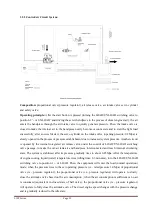
1.2.3 Oil Circuit System:
Composition:
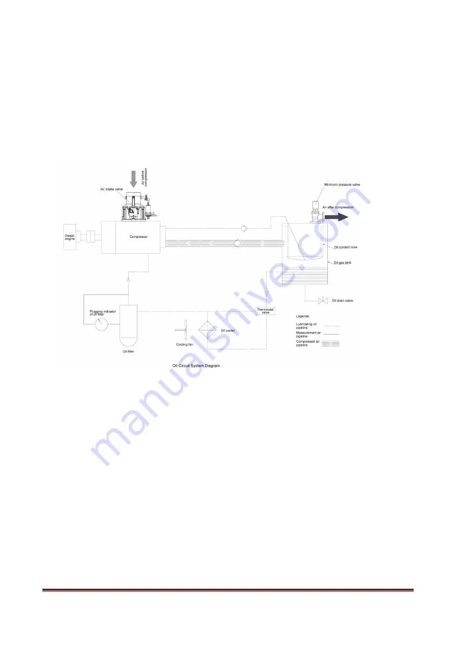
The oil circuit system is composed of oil cooler, oil filter, oil-air tank, oil content core
and thermostat valve.
Operating principle:
For the oil circuit system without oil pump, the lubricating oil relies on the
pressure difference between the exhaust port of the compressor and the fuel injection port of the main
engine to maintain the flow in the circuit. When the equipment operates, the lubricating oil in the oil-air
tank enters the oil cooler under the action of differential pressure. After cooled and removed of
impurities and particles by the oil filter, most of lubricating oil is injected into the compression chamber
of compressor, and the remaining lubricating oil is distributed to the bearing and shaft seal, etc. to
function as lubrication, sealing, cooling and noise reduction. At last, all lubricating oil is discharged into
the oil-air tank with the compressed air to separate most of lubricating oil for recycling. A small amount
of lubricating oil separated by the oil content core is also brought back to the low-pressure position such
as air intake port.
Function:
The oil is mainly used to seal the compressed air and to remove the heat generated during the
process of compressing the air.
A. Oil cooler
Содержание JCD-900 Series
Страница 1: ...DIESEL ENGINE PORTABLE ROTARY SCREW AIR COMPRESSOR INSTRUCTION MANUAL Model LGCY27 10 LGCY32 10SERIES...
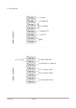
Страница 25: ...LGCY Series Page 23 8 Wiring diagram...
Страница 31: ...LGCY Series Page 29...
Страница 34: ...LGCY Series Page 32 during stop...

