6-21 (E)
SRX-R515P
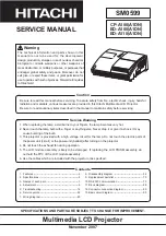
3D unit assembly
Stopper
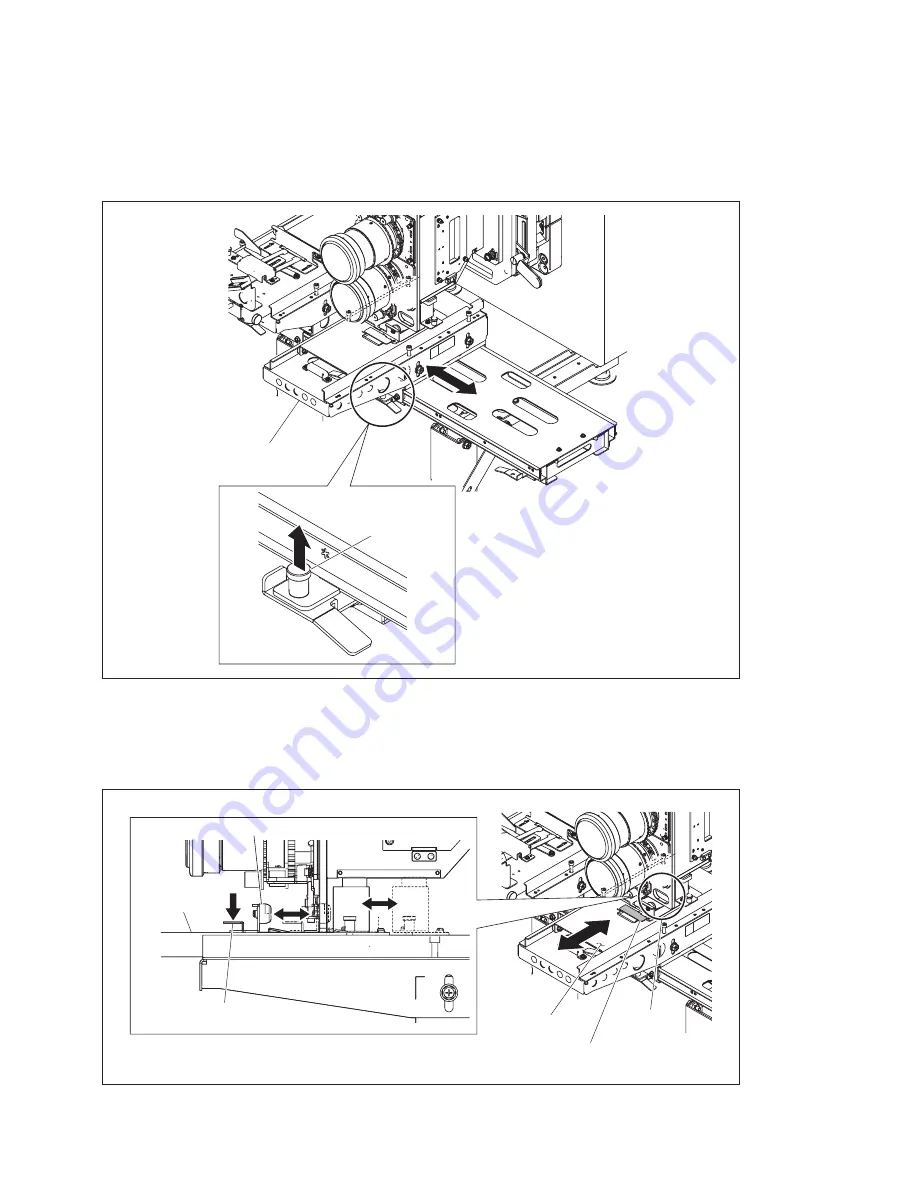
Lens base
Lock lever
Hole
Lens base
Lock lever
Boss
6-4-3. Check after Adjustment
1. Lift up the stopper and move the 3D unit assembly from side to side. Check that the 3D unit assembly
can be moved smoothly.
2. Move the lens base back and forth with the lock lever pushed in. Check that the two bosses can be
smoothly inserted into and removed from the hole under the 3D lens.
If the bosses cannot be smoothly inserted into and removed from the hole, perform “6-4-2. Height
Adjustment of 3D Unit Assembly” again.
Содержание SRX-R515P
Страница 4: ......
Страница 8: ......
Страница 20: ......
Страница 25: ...2 5 E SRX R515P 3D filter R assembly Knob Knob 3 Attach the 3D filter R assembly with the two knobs ...
Страница 30: ...2 10 E SRX R515P Touch panel monitor Screw Screw Screw 4 Attach the touch panel monitor with the three screws ...
Страница 44: ......
Страница 50: ......
Страница 145: ......