6-4
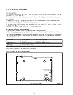
2. ELECTRICAL ADJUSTMENT
VCR PRESETTING
This VCR need three basic presetting by using the menus displayed on-screen. After all connection have been made, then
follow steps 1 to 3 to preset the VCR.
The three presetting steps will be displayed in sequence on TV screen. The setting are entered with the remote control.
Turn on the VCR
1. Adjusting the TV receiver to the video channel: The AUTO SETUP screen will appear. When the video channel has
been preset, press the OK button on the remote control.
2. Country selection: Using the numeric button, select the country of use.
3. Language selection: When the desired language has been select, press the MENU / TV button directly before prevent
auto tuning will start.
When steps 1 to 3 have been finish, ready to operate the all operating mode.
2-1. SERVO CIRCUIT ADJUSTMENT
• These adjustments should be done upon completion of the tape transport adjustments.
• If the tape transport adjustments (except the tilt adjustment) are done after these adjustments, follow the procedures
again in section 2-1-3, “switching position adj.”
• When a cassette tape is loaded, auto-tracking will be set immediately after starting the first playback. As this will daviate
the tracking center set, be sure to press the channel buttons (
4
) or (
$
) once directly after starting playback to prevent
auto-tracking from being set.
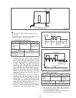
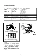
Oscilloscope
Vertical sensitivity
: 5 mV/DIV, external trigger
Bandwidth
: more than 10 MHz
Alignment Tape
KRV-51P (8-192-605-36)
: SP mode, monoscope. 400 Hz
Blank Tape
VHS-type cassette tape
Monitor TV
CP-1 PWB (Foil side)
Fig. 2-1-1
VR351
VR631
TP633
VR634
VR632
VR635
VR633
TP631
TP635
SLV-L65HFAR/L75HFAR only
TP101
2-1-1. TEST EQUIPMENT AND STANDARDS REQUIRED
2-1-2. LOCATION OF ADJUSTMENT POINTS
Содержание SLV-L45AR
Страница 6: ...1 2 ...
Страница 7: ...1 3 ...
Страница 8: ...1 4 ...
Страница 9: ...1 5 ...
Страница 10: ...1 6 ...
Страница 11: ...1 7 ...
Страница 12: ...1 8 E ...
Страница 17: ...3 2 MECHANISM CONNECTION DIAGRAM ...
Страница 18: ...3 3 3 4 SLV L45AR L65HFAR L75HFAR OVERALL WIRING DIAGRAM SLV L45AR ...
Страница 19: ...SLV L45AR L65HFAR L75HFAR OVERALL WIRING DIAGRAM SLV L65HFAR L75HFAR 3 5 3 6 ...
Страница 20: ...3 7 3 8 SLV L45AR L65HFAR L75HFAR SYSTEM CONTROL SERVO CIRCUIT DIAGRAM SLV L45AR ...
Страница 21: ...3 9 3 10 SLV L45AR L65HFAR L75HFAR SYSTEM CONTROL SERVO CIRCUIT DIAGRAM SLV L65HFAR L75HFAR ...
Страница 22: ...3 11 3 12 SLV L45AR L65HFAR L75HFAR VIDEO CIRCUIT DIAGRAM SLV L45AR AUDIO CIRCUIT DIAGRAM SLV L45AR ...
Страница 25: ...SLV L45AR L65HFAR L75HFAR 4 3 4 4 CP 1 BOARD VA A VIDEO AUDIO TUNER CIRCUIT DIAGRAM SLV L45AR ...
Страница 26: ...SLV L45AR L65HFAR L75HFAR 4 5 4 6 CP 1 BOARD VA A VIDEO AUDIO TUNER CIRCUIT DIAGRAM SLV L65HFAR L75HFAR ...
Страница 27: ...SLV L45AR L65HFAR L75HFAR 4 7 4 8 VIDEO CIRCUIT WAVEFORMS VP 1 BOARD VIDEO PRE AMP CIRCUIT DIAGRAM SLV L45AR ...
Страница 32: ...SLV L45AR L65HFAR L75HFAR 4 17 4 18 CP 1 BOARD SY A SYSTEM CONTROL SERVO CIRCUIT DIAGRAM SLV L45AR ...
Страница 33: ...4 19 4 20 CP 1 BOARD SY A SYSTEM CONTROL SERVO CIRCUIT DIAGRAM SLV L65HFAR L75HFAR ...


