5-25
4. MECHANISM CHECKS AND
ADJUSTMENTS
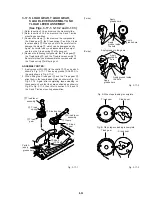
4-1. REEL TABLE TORQUE CHECK
1) With the power switch turned OFF, stick black vinyl tape
over the photo diodes of the tape sensors. Then turn
the power switch ON. Front loading will begin. Refer to
section 3-2 and Fig. 3-2-2. and release the locks of the
tray lock lever and the lid opener lever.
NOTES:
1. The measurements must be taken without any incan-
descent light or daylight.
2. If the mechanism cannot be put into PLAY, FF or REW
mode by the method described in 1) above, make a
dummy cassette tape, as shown in Fig. 4-1-2. The dummy
cassette tape is made as follows: Unscrew the five screws
on the underside, remove the reels, leaf springs and other
parts on the supply and take up sides, make holes in the
upper surface as wide as the reel diameter, then assemble
the parts.
2) Put the mechanism into REW mode, wait at least 10 sec-
onds, then measure the torque value of the reel table on
the supply side. It should be at least 600 g/cm. Take the
measurement with the torque dial gauge (H-7099-039-H/
H-7099-035-H) held in position in your hand (lock torque).
While taking the measurement, rotate the reel table (take
up reel assembly) on the take up side with your hand so
that the reel sensor does not respond.
3) After switching to FF mode, wait for at least 10 seconds
and then measure the torque value of the reel table on
the take up side. It should be at least 600g/cm (lock
torque).
4) After switching to PLAY mode, wait for at least 10
seconds and then measure the torque value of the reel
table on the take up side. It should be between 80 and
140g/cm (lock torque).
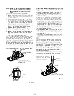
Torque dial gauge
(H-7099-039-H)
(H-7099-035-H)
Reel table on
supply side
Reel table on
take up side
Fig. 4-1-1
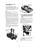
Stick black vinyl
tape over the tape
sensor holes.
Dummy cassette
tape
Make holes with
roughly the same
diameter as the reel.
Fig. 4-1-2
4-2. ADJUSTING THE BT LEVER ASSEM-
BLY POSITION AND CHECKING THE
BACK TENSION TORQUE IN PLAY
MODE
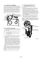
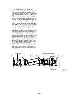
4-2-1. BT LEVER POLE POSITION ADJUSTMENT
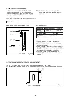
(See Fig. 4-2-1 )
1) Without loading a cassette tape, put the mechanism into
PLAY mode (turn the power switch OFF).
2) Adjust point
A
on the band brake assembly by rotating
it so that the tip of the BT lever assembly is aligned with
the line on the left side of the mechanism chassis.
3) Refer to section 4-2-2 and check that the back tension
torque is between 30 and 50g/cm.
Align the end of the BT lever
assembly with this line.
BT lever assembly
Tension
pole
Point
A
Fig. 4-2-1
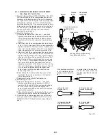
4-2-2. CHECKING THE BACK TENSION TORQUE
PLAY MODE
1) Mount the cassette torque meter (VHT-063S) and
switch to PLAY mode.
2) Check that the back tension torque is between 30 and
50g/cm .
Содержание SLV-L45AR
Страница 6: ...1 2 ...
Страница 7: ...1 3 ...
Страница 8: ...1 4 ...
Страница 9: ...1 5 ...
Страница 10: ...1 6 ...
Страница 11: ...1 7 ...
Страница 12: ...1 8 E ...
Страница 17: ...3 2 MECHANISM CONNECTION DIAGRAM ...
Страница 18: ...3 3 3 4 SLV L45AR L65HFAR L75HFAR OVERALL WIRING DIAGRAM SLV L45AR ...
Страница 19: ...SLV L45AR L65HFAR L75HFAR OVERALL WIRING DIAGRAM SLV L65HFAR L75HFAR 3 5 3 6 ...
Страница 20: ...3 7 3 8 SLV L45AR L65HFAR L75HFAR SYSTEM CONTROL SERVO CIRCUIT DIAGRAM SLV L45AR ...
Страница 21: ...3 9 3 10 SLV L45AR L65HFAR L75HFAR SYSTEM CONTROL SERVO CIRCUIT DIAGRAM SLV L65HFAR L75HFAR ...
Страница 22: ...3 11 3 12 SLV L45AR L65HFAR L75HFAR VIDEO CIRCUIT DIAGRAM SLV L45AR AUDIO CIRCUIT DIAGRAM SLV L45AR ...
Страница 25: ...SLV L45AR L65HFAR L75HFAR 4 3 4 4 CP 1 BOARD VA A VIDEO AUDIO TUNER CIRCUIT DIAGRAM SLV L45AR ...
Страница 26: ...SLV L45AR L65HFAR L75HFAR 4 5 4 6 CP 1 BOARD VA A VIDEO AUDIO TUNER CIRCUIT DIAGRAM SLV L65HFAR L75HFAR ...
Страница 27: ...SLV L45AR L65HFAR L75HFAR 4 7 4 8 VIDEO CIRCUIT WAVEFORMS VP 1 BOARD VIDEO PRE AMP CIRCUIT DIAGRAM SLV L45AR ...
Страница 32: ...SLV L45AR L65HFAR L75HFAR 4 17 4 18 CP 1 BOARD SY A SYSTEM CONTROL SERVO CIRCUIT DIAGRAM SLV L45AR ...
Страница 33: ...4 19 4 20 CP 1 BOARD SY A SYSTEM CONTROL SERVO CIRCUIT DIAGRAM SLV L65HFAR L75HFAR ...


