background image

1-7

Содержание SLV-L45AR

Страница 1: ...entrada 327 m Vrms Impedancia de entrada superior a 47 kiloohmios LINE OUT VIDEO OUT Toma fonográfica 1 Señal de Salida 1 Vp p 75 ohmios desequilibrada sincronización negativa AUDIO OUT Tomas fonográficas 2 L R SLV L65HFAR L75HFAR Toma fonográfica 1 SLV L45AR Salida estándar 327 m Vrms Impedancia de carga 47 kiloohmios Impedancia de salida inferior a 10 kiloohmios General Requisitos de alimentació...

Страница 2: ...k for unauthorized replacement parts particularly tran sistors that were installed during a previous repair Point them out to the customer and recommend their replacement SAFETY RELATED COMPONENT WARNING COMPONENTS IDENTIFIED BY MARK OR DOTTED LINEWITH MARK ONTHE SCHEMATIC DIAGRAMS AND INTHE PARTS LIST ARE CRITICALTO SAFE OPERATION REPLACE THESE COMPONENTS WITH SONY PARTS WHOSE PART NUMBERS APPEAR...

Страница 3: ...OF CONTENTS Section Title Page ______ ____ ____ Section Title Page ______ ____ ____ Servo Circuit Waveforms 4 15 IC 301 System Control Tuning Control MPU Pin Functions Table 4 16 CP 1 Board SY A System Control Servo Circuit Diagram SLV L45AR 4 17 CP 1 Board SY A System Control Servo Circuit Diagram SLV L65HFAR L75HFAR 4 19 5 ADJUSTMENTS 1 Maintaining and Checking the Mechanism 5 1 l 1 Regular Chec...

Страница 4: ... 5 26 4 3 3 Guide Roller Height Adjustment 5 27 4 3 4 Audio R P Head ACE HEAD Height Adjustment Azimuth Adjustment and Horizontal Position Adjustment 5 28 4 3 5 Checking After Adjustment 5 29E 6 ELECTRICAL ADJUSTMENTS Circuit Boards Location 6 1 Self Diagnosis Display 6 2 1 Self Diagnosis Contents and Mechanism Mode Display 6 2 2 Electrical Adjustment 6 4 2 1 Servo Circuit Adjustment 6 4 2 1 1 Tes...

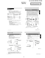
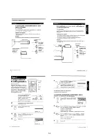
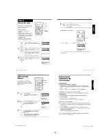
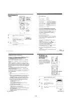
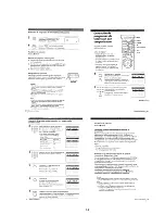
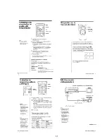
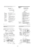
Страница 5: ...1 1 SECTION 1 GENERAL SLV L45AR L65HFAR L75HFAR This section is extracted from SLV L75HFAR instruction manual ...

Страница 6: ...1 2 ...

Страница 7: ...1 3 ...

Страница 8: ...1 4 ...

Страница 9: ...1 5 ...

Страница 10: ...1 6 ...

Страница 11: ...1 7 ...

Страница 12: ...1 8 E ...

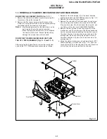
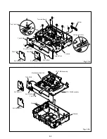
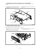
Страница 13: ...ut the lock clamps C in the arrow direction slightly and remove the TM 1 PWB as shown in Fig 1 1 2 2 Remove the screw 4 at the chassis 3 Remove the red screw 5 in the chassis the red screw 6 and remove the holder in this order SLV L45AR Remove the screw 5 in the chassis the screw 6 and the holder in this order SLV L65HFAR L75HFAR 4 Remove the two screws 7 and two screws 8 of the mechanism unit The...

Страница 14: ...pener Lever A Tray Lock Lever Cassette Tray C C Terminal Board C C B TM 2 PWB SLV L75HFAR SLV L45AR B TM 2 PWB SLV L65HFAR TM 2 PWB Fig 1 1 3 Mechanism Main Unit TM 1 PWB Clamps D Chassis CP 1 PWB Assembly VP 1 PWB Assembly TM 2 PWB SLV L45AR SLV L75HFAR SLV L65HFAR ...

Страница 15: ...to half opened state as shown in Fig 1 1 5 and install the front panel to the chassis Note Opened cassette door position does not install the front panel to the chassis Fig 1 1 5 Jutted part of Cassette Holder Door Opener Lever Front Panel Cassette Door Position B Cassette Door Position A E 1 2 TEMPORARILY SETTING UP AND CONNECTING CP 1 PWB ASSEMBLY The following is an example of how to place and ...

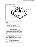
Страница 16: ...3 1 SECTION 3 DIAGRAMS SLV L45AR L65HFAR L75HFAR CIRCUIT BOARDS LOCATION CP 1 PWB Assembly TM 1 PWB TM 2 PWB VP 1 PWB Assembly 3 in 1 Tuner Tuner IF RF Conv ...

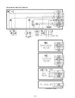
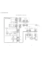
Страница 17: ...3 2 MECHANISM CONNECTION DIAGRAM ...

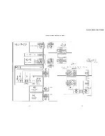
Страница 18: ...3 3 3 4 SLV L45AR L65HFAR L75HFAR OVERALL WIRING DIAGRAM SLV L45AR ...

Страница 19: ...SLV L45AR L65HFAR L75HFAR OVERALL WIRING DIAGRAM SLV L65HFAR L75HFAR 3 5 3 6 ...

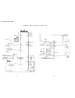
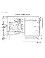
Страница 20: ...3 7 3 8 SLV L45AR L65HFAR L75HFAR SYSTEM CONTROL SERVO CIRCUIT DIAGRAM SLV L45AR ...

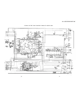
Страница 21: ...3 9 3 10 SLV L45AR L65HFAR L75HFAR SYSTEM CONTROL SERVO CIRCUIT DIAGRAM SLV L65HFAR L75HFAR ...

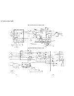
Страница 22: ...3 11 3 12 SLV L45AR L65HFAR L75HFAR VIDEO CIRCUIT DIAGRAM SLV L45AR AUDIO CIRCUIT DIAGRAM SLV L45AR ...

Страница 23: ...3 13 3 14E SLV L45AR L65HFAR L75HFAR AUDIO CIRCUIT DIAGRAM SLV L65HFAR L75HFAR VIDEO CIRCUIT DIAGRAM SLV L65HFAR L75HFAR ...

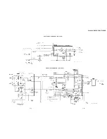
Страница 24: ...SLV L45AR L65HFAR L75HFAR 4 1 4 2 SECTION 4 SCHEMATIC DIAGRAMS AND PRINTED WIRING BOARDS CP 1 BOARD PW A POWER SUPPLY CIRCUIT DIAGRAM ...

Страница 25: ...SLV L45AR L65HFAR L75HFAR 4 3 4 4 CP 1 BOARD VA A VIDEO AUDIO TUNER CIRCUIT DIAGRAM SLV L45AR ...

Страница 26: ...SLV L45AR L65HFAR L75HFAR 4 5 4 6 CP 1 BOARD VA A VIDEO AUDIO TUNER CIRCUIT DIAGRAM SLV L65HFAR L75HFAR ...

Страница 27: ...SLV L45AR L65HFAR L75HFAR 4 7 4 8 VIDEO CIRCUIT WAVEFORMS VP 1 BOARD VIDEO PRE AMP CIRCUIT DIAGRAM SLV L45AR ...

Страница 28: ...SLV L45AR L65HFAR L75HFAR 4 9 4 10 VP 1 P W B VP 1 BOARD VIDEO PRE AMP CIRCUIT DIAGRAM SLV L65HFAR L75HFAR r There are few cases than the part isn t mounted in this model is printed on this diagram ...

Страница 29: ...SLV L45AR L65HFAR L75HFAR 4 11 4 12 TM 1 TM 2 BOARDS OPERATION KEY DISPLAY TIMER CIRCUIT DIAGRAM SLV L45AR GRID SEGMENT ASSIGNMENT ANODE CONNECTION A7101 DISPLAY FLD GRID ANODE ASSIGNMENT DRAWING TABLE ...

Страница 30: ...M 1 TM 2 BOARDS OPERATION KEY DISPLAY TIMER CIRCUIT DIAGRAM SLV L65HFAR L75HFAR r There are few cases than the part isn t mounted in this model is printed on this diagram r There are few cases than the part isn t mounted in this model is printed on this diagram ...

Страница 31: ...SLV L45AR L65HFAR L75HFAR SERVO CIRCUIT WAVEFORMS IC301 SYSTEM CONTROL TUNING CONTROL MPU PIN FUNCTIONS TABLE 4 15 4 16 ...

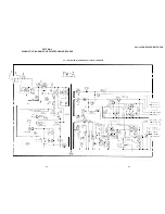
Страница 32: ...SLV L45AR L65HFAR L75HFAR 4 17 4 18 CP 1 BOARD SY A SYSTEM CONTROL SERVO CIRCUIT DIAGRAM SLV L45AR ...

Страница 33: ...4 19 4 20 CP 1 BOARD SY A SYSTEM CONTROL SERVO CIRCUIT DIAGRAM SLV L65HFAR L75HFAR ...

Страница 34: ...SLV L45AR L65HFAR L75HFAR 4 22E 4 21 r There are few cases than the part isn t mounted in this model is printed on this diagram CP 1 P W B ...

Страница 35: ...0 2500 3000 3500 4000 4500 5000 Remarks Tape guide ACE head full erase head Tape path Cylinder drum system Cleaner roller assembly Pinch roller Reel table Drive Reel belt system Relay gear Pulley shaft Gear shaft Loading motor Back tension Perform Brake system ance checks FWD REW PLAY torque REV torque The life of parts varies enormously depending on the environment in which the part is used Playb...

Страница 36: ...easure reel winding torque 8 Torque dial gauge adaptor H 7099 035 H Used to measure reel winding torque 9 Cassette torque meter VHJ 063S J 6082 011 A Used to measure back tension torque 10 Load lever assembly height adjustment tool J 6090 055 A Used to adjust the height of the load lever assembly 11 Torque gauge screwdriver J 6082 047 A Used to adjust the tightening torque of screws 12 3 mm dia bi...

Страница 37: ...TE 1 Do not place the mechanism upright as shown in Fig 1 3 1 when inserting ejecting the cassette NOTE 2 For NTSC models be sure to connect the VM 1 PWB assembly and CP 1 PWB assembly Mechanism unit CP 1 PWB assembly VM 1 VP 1 PWB assembly Relay cable J 6090 057 A Fig 1 2 2 Fig 2 1 1 2 AN OVERVIEW OF THE MECHANISM 2 1 NAMES OF THE MAIN PARTS 2 1 1 CASSETTE MECHANISM ASSEMBLY Under frame Stand L R...

Страница 38: ... soft lever Supply reel assembly Band brake assembly BT spring Tape sensor LED BT lever assembly Tape end sensor Guide roller assembly S incline mounting assembly Full erase head T incline mounting assembly Guide roller assembly Cylinder mounting Fig 2 1 2 Fig 2 1 3 Stator Rotor T load gear S load gear Crescent mounting T load lever assembly S load lever assembly BT spring lever assembly MC 1 PWB ...

Страница 39: ... T mounting incline assembly pressure begins S T mounting incline assembly pressure ends REVIEW 1 IDLER pos 2 Pinch roller OFF STILL SLOW 3 PLAY STOP 5 BRAKE pos 4 FF REW 6 CASSETTE OUT EJECT IN REW SHORT REW INITIAL POWER OFF The principal mode switching states of the mechanism Mechanism mode HEX DATA When loading is carried out starting at the CASSETTE IN position REVIEW STILL SLOW REC PAUSE REC...

Страница 40: ...fore performing repairs For details refer to the separate service manual for the respective models 6 FF REW 4 BRAKE 5 PLAY STOP 3 STILL SLOW 2 IDLER 1 REVIEW 7 INITIAL POWER OFF E EJECT Crescent slide Crescent mounting The edge of the crescent mounting is the reference line Fig 2 2 2 S Strength W Weakness T brake assembly OFF OFF ON ON ON OFF OFF OFF OFF ON ON OFF S brake assembly OFF OFF OFF OFF ...

Страница 41: ...rotation of the loading motor before beginning front unloading Rotate the capstan motor with your hand wind the slacked part of the tape and rotate the loading motor in the EJECT direction again NOTE 1 When carrying out front loading release the lock by pressing down the tray lock lever 8 and the lid opener lever 9 of the cassette mechanism assembly shown in Fig 3 2 2 in the direction of the arrow...

Страница 42: ...r lever 8 Tray lock lever 7 Tray Fig 3 2 2 3 3 CASSETTE DRIVE MECHANISM 3 3 1 CASSETTE MECHANISM ASSEMBLY See Figs 3 3 1 and 3 3 2 1 Put the VCR into EJECT mode 2 Remove the two screws 1 3 Lift up the back of the cassette mechanism assembly 2 slightly and remove the two hooks 3 on the front ASSEMBLY NOTES 1 The cassette mechanism assembly and the mechanism chassis should both be fitted in EJECT mo...

Страница 43: ...sembly referring to section 3 1 2 Remove the two clamps 1 and take out the under frame 2 pulling it towards you 3 Press down the tray lock lever 3 and the lid opener lever 4 and loosen the tray 5 lifting it away from you In this state press the clamp 6 and remove the door opener lever 7 4 Remove the two clamps 8 and take out the stand L 9 Be careful not to exert too much force on the clamps 8 as t...

Страница 44: ... to section 3 3 1 and align the start rack gear with the pinion gear 6 Clamp 1 Special screw 4 Spring 7 Start rack gear apply grease to inside of groove 5 Front rack gear apply grease to inside of groove 3 Shaft 2 Front rack gear assembly Fig 3 3 5 8 Positioning mark 5 Front rack gear 0 Positioning mark 9 Main cam Flg 3 3 6 3 4 CLEANER ROLLER ASSEMBLY See Fig 3 4 1 1 Remove the clamp 1 and take ou...

Страница 45: ...o the switching position adjustment of the servo circuit 3 Screws 4 Rotor 9 Long hole used for alignment when fitting the rotor Triangular mark 5 Screws 6 Stator 8 Spacer 1 Screws 2 Cylinder earth assembly Dowels Holes 0 Hole Use for alignment when fitting the rotor Fig 3 5 1 3 5 2 CYLINDER ASSEMBLY See Fig 3 5 2 1 Refer to sections 3 5 2 and remove the cylinder unit the rotor and the stator 2 Rem...

Страница 46: ...eaner roller assembly has snapped into the mounting of the audio R P head assembly ACE head 2 3 After assembly clean the surface of the head with a soft cloth or chamois 4 After assembly refer to section 4 3 and adjust the head height the azimuth and the tracking X position 1 Screws 2 Audio R P head assembly ACE head 3 Hole 5 Clamp 4 Pin Fig 3 6 1 3 6 2 FULL ERASE HEAD See Fig 3 6 2 1 Unplug the c...

Страница 47: ...in the CP 1 PWB assembly 2 When fitting the thre screws 5 use the torque gauge screwdriver J 6082 047 A Give the screws a tighten ing torque of 3 5 kg cm 3 After assembly clean the capstan shaft with a soft cloth or chamois 5 Screws 6 Capstan motor 4 Connector 1 Harness mounting 2 Screws 3 Reel belt Capstan shaft Fig 3 7 1 3 7 2 CAPSTAN BRAKE ASSEMBLY See Fig 3 7 2 1 Remove the spring 1 2 Remove t...

Страница 48: ...rity of the lead wires 2 the orange wire is the positive terminal and the gray wire is the nega tive terminal After soldering the lead wires 2 adjust them so that they do not touch the friction gear assem bly 5 Worm gear assembly 6 Clamps 1 Loading motor assembly 2 Lead wires 3 Clamp 4 Damper Gray negative Orange positive Apply grease Fig 3 8 1 3 9 PINCH ROLLER PRESSURE MECHANISM 3 9 1 PINCH ROLLE...

Страница 49: ...ver the top cam D of the pinch cam gear 6 2 Check that the positioning mark 0 on the mode switch 9 is aligned with the arrow on the MC 1 PWB assembly as shown in Fig 3 9 3 Then align the triangular mark on the pinch cam gear 6 with the arrow on the MC 1 PWB assembly After that align the round hole on the pinch lift cam 5 with the indentation on the pinch cam gear 6 If you have carried out the abov...

Страница 50: ... Shaft 9 Shaft A Stopper Cam groove Fig A Fig 3 10 1 3 11 BT LEVER ASSEMBLY See Fig 3 11 1 1 Refer to section 3 2 and remove the mechanism unit 2 Refer to section 3 3 1 and remove the cassette mecha nism assembly 3 Remove the BT spring 1 4 Remove the clamp 2 on the underside of the mecha nism chassis then remove the BT lever assembly 3 5 Remove the clamp 5 on the band brake assembly 4 Then as show...

Страница 51: ... nism assembly 2 Refer to section 3 12 1 and remove the reel pulley 3 Remove the two screws 1 then remove the clutch mounting assembly 2 ASSEMBLY NOTES 1 Align the two holes 3 with the shafts 4 and 5 Be careful not to press part A of the clutch mounting assembly 2 against the band brake assembly 2 After assembly make sure that the clamp on the clutch change lever has snapped into the chassis 1 Scr...

Страница 52: ...12 4 3 13 BRAKES 3 13 1 S BRAKE ASSEMBLY T BRAKE ASSEM BLY T BRAKE ACT SLIDE See Fig 3 13 1 1 Refer to section 3 3 1 and remove the cassette mecha nism assembly 2 Remove the two clamps 1 then remove the T brake act slide 2 Note You can remove the S brake assem bly 7 and the T brake assembly 5 without removing the T brake act slide 2 3 Remove the brake spring 3 4 Remove the two clamps 4 simultaneou...

Страница 53: ...rake control lever 8 Clamp 5 Clamp 0 Shaft Shaft Hole 4 Clamp Hole 1 Clamp 2 Wheel gear 1 3 Clutch change spring 9 Brake act lever assembly 7 Brake return spring Cam groove Fig 3 13 2 3 13 3 S BRAKE ACT SLIDE AND BT SPRING LEVER ASSEMBLY See Figs 3 13 3 and 3 13 4 1 Refer to section 3 16 and remove the crescent slide 2 Refer to section 3 12 1 and remove the friction gear assembly 3 Slide the S bra...

Страница 54: ...ading is completed 5 Shift the S incline mounting assembly 1 slightly in the direction of the arrow A then remove it from the S load lever assembly 2 6 Shift the T incline mounting assembly 3 slightly in the direction of the arrow B then remove it from the T load lever assembly 4 ASSEMBLY NOTES 1 Apply grease SGL 505 to the rail top underside and sides on the mechanism chassis 2 When fitting the S...

Страница 55: ... B refer to section 3 9 2 and check the positioning of the mode switch the pinch cam gear and the pinch lift cam 3 Beforehand remove the soldering from the soldered part of the MC 1 PWB assembly in order to prevent the mode switch 6 being warped Solder the mode switch 6 after tightening the screw 5 See Fig 3 15 1 4 Align the hole in the crescent slide with the hole in the mechanism chassis as show...

Страница 56: ... in Fig 3 16 1 and to the crescent slide 3 shown in Fig 3 16 2 2 Before fitting the crescent slide 3 refer to section 3 13 3 and align the arrow on the S brake act slide with the arrow on the mechanism chassis Then refer to Fig 3 17 3 and check that the S load gear and the T load gear have completed tape unloading 3 When assembling the parts raise the right side of the crescent slide 3 slightly an...

Страница 57: ...Y NOTES 1 Apply grease SGL 505 to the shafts 8 9 and parts A shown in Fig 3 17 1 Then apply grease SGL 505 to the parts shown in Fig 3 17 2 2 When fitting the S load gear 2 and the T load gear 5 align them in the tape loaded state as shown in Fig A in Fig 3 17 3 Again after completing tape unloading on these gears check that they are positioned as shown in Fig B in Fig 3 17 3 then refer to section...

Страница 58: ...SENSOR See Fig 3 18 2 1 Refer to sections 3 12 2 and 3 12 4 then remove the clutch mounting assembly the T soft brake assembly and the take up reel assembly 2 Refer to section 3 13 2 then remove the wheel gear 2 the wheel gear 1 and the brake control lever 3 Remove the soldering from the MC 1 PWB assembly then remove the photo diode reel sensor 1 ASSEMBLY NOTES 1 When assembling the parts align th...

Страница 59: ...l sensor does not respond 3 After switching to FF mode wait for at least 10 seconds and then measure the torque value of the reel table on the take up side It should be at least 600g cm lock torque 4 After switching to PLAY mode wait for at least 10 seconds and then measure the torque value of the reel table on the take up side It should be between 80 and 140g cm lock torque Torque dial gauge H 70...

Страница 60: ...veform test point and bring the CH 2 probe into contact with the switching pulse SW P test point While adjusting the tape path set the trigger at the low side of the switching pulse SW P in order to observe the output waveform on the CH 1 side of the video head NOTE The contact point for the oscilloscope varies from one model to another so to find the correct point for your model refer to the figu...

Страница 61: ...that when you tighten the S guide roller the wrapper waveform does not disappear but sinks into the flat part as shown in Fig 4 3 4 d If this happens the status shown in Fig 4 3 4 c is normal so loosen the S guide roller then tighten it again until the envelope waveform is as shown in Fig 4 3 4 c 2 Check that at the tracking centre the output of the front half of the envelope waveform is not less ...

Страница 62: ...ent See Fig 4 3 6 1 Play the alignment tape NTSC KRV 52NE PAL KRV 52PL 2 Press the tracking buttons channel and channel simultaneously and set the tracking to the centre 3 Using an oscilloscope observe the waveform of the video head output 4 Loosen the two fixed screws on the audio R P head ACE head by between 20 and 30 anticlockwise 5 Using a slotted screwdriver adjust the position of the audio R...

Страница 63: ... envelope waveform amplitude is at its maximum 3 Check that the envelope waveform is activated immedi ately when you switch from PLAY to R SEARCH or from R SEARCH to PLAY Check that there is no slack in the tape next to the pinch roller 4 Check that the envelope waveform is activated immedi ately when you switch to PLAY from FF REW F SEARCH R SEARCH or STOP mode Check that there is no slack in the...

Страница 64: ...6 1 SECTION 6 ELECTRICAL ADJUSTMENTS CIRCUIT BOARDS LOCATION CP 1 PWB Assembly TM 1 PWB TM 2 PWB VP 1 PWB Assembly 3 in 1 Tuner Tuner IF RF Conv SLV L45AR L65HFAR L75HFAR ...
Страница 65: ...mechanism mode numbers When the 0 button on the remote control unit is pressed during display and clearing the self diagnosis display and mechanism mode display No Problem Main Possible Cause Mechanism Operations and State After Occurrence 00 There is no abnormality in the mechanism The cylinder motor does not rotate The cylinder motor is faulty Shifts to the STOP mode 01 The control of the cylind...

Страница 66: ... The mechanism becomes 7 INITIAL The mechanism mode switch Carries out tape take up operations 09 while moving from 1 REVIEW contact is faulty shifts to the INITIAL mode 2 IDLER 3 STILL 4 BRAKE and the power goes off and to 5 STOP The capstan motor does not rotate The capstan motor is faulty Shifts to the STANDBY mode 10 and cassette tape eject when The control of the capstan motor is Protect cass...

Страница 67: ...e the all operating mode 2 1 SERVO CIRCUIT ADJUSTMENT These adjustments should be done upon completion of the tape transport adjustments If the tape transport adjustments except the tilt adjustment are done after these adjustments follow the procedures again in section 2 1 3 switching position adj When a cassette tape is loaded auto tracking will be set immediately after starting the first playbac...

Страница 68: ...6 5 H 0 5 H from the fall down point of RF SW PULSE Fig 2 1 4 4 After the adjustment data is fixed it should be within 15 seconds from the adjustment mode start press the PLAY button more than 1 second Then the indication changes to P it writes the data delay quantity to theE2 PROM If it passes through 15 seconds before pushing the PLAY button the intake of the data isn t done and it finishes the ...

Страница 69: ...B assembly using the relay jig to provide simple repairing of the VP 1 PWB assembly as shown in Fig 2 2 3 Further when adjusting the VP 1 PWB assem bly be sure to make contact an end of shield case with bracket of the VP 1 PWB assembly to maintain the shield effect If the VP 1 PWB assembly does not contact there is insufficient ground and no proper play back image can be obtained Color bar signal ...

Страница 70: ...ut frequency 20 Hz 10MHz AC Voltmeter DC Voltmeter DC Power Supply Unit Voltage 0 15 V DC Band Path Filter 200 Hz 15 kHz CP 1 PWB Foil side VR351 VR631 TP633 VR634 VR632 VR635 VR633 TP631 TP635 TP101 Fig 2 3 1 2 3 2 LOCATION OF ADJUSTMENT POINTS 2 3 MTS DECODER CIRCUIT ADJUSTMENT If adjusting the MTS Decoder Circuit special equipment shown in section 2 2 1 is necessary Improper adjustment will cau...

Страница 71: ...he value down 5 Set ON the pilot switch and confirm that ST within the indicator panel lights If not adjust VR635 VCO until ST lights 6 Measure the output voltage of TP635 and adjust VR635 VCO so that the output voltage agree with the value within 0 03 V measured in step 3 2 3 5 INPUT LEVEL ADJ 1 Input the output signal of the TV multichannel sound generator into the VCR ANT input terminal 2 Set t...

Страница 72: ... VCR ANT input terminal Set the TV multi channel sound generator INT FREQ switch 300 Hz STEREO switch L R SAP switch ON PILOT switch ON 2 Receive the signal of TV multichannel sound generator and confirm so that the L R within the monitor TV when PILOT switch to ON 3 Confirm ST and SAP within the VCR indicator panel lights 4 Confirm the waveform of the AUDIO OUTPUT terminal L and R on the oscillos...

Страница 73: ...cal field 70 dBµ 90 dBµ of the VHF or UHF channel and slowly turn the VR RF AGC from the point where snow noise is present to the point where it just disappears from the monitor TV 4 Confirm by monitor TV that there is no beat and saturation S N is best point when receiving any TV channel Measuring Point Measuring Equipment Adj Condition Picture of Monitor TV E E mode monitor TV Adj Location Adj V...

Страница 74: ...01 BTS B S 4X12 10 3 051 087 01 COVER TOP L75HFAR 10 3 051 290 01 COVER TOP L45AR 10 3 976 260 01 COVER TOP L65HFAR 11 3 963 641 01 HOLDER AC INLET 12 3 963 642 01 TOP HOLDER COVER 13 3 963 620 01 COVER BOTTOM 14 3 942 661 01 STAND FELT 15 A 6794 547 A TM 2 BOARD COMPLETE L75HFAR 15 A 6794 561 A TM 2 BOARD COMPLETE L65HFAR 15 A 6794 569 A TM 2 BOARD COMPLETE L45AR 16 3 051 090 01 BUTTON 2P L75HFAR...

Страница 75: ... 70 71 72 73 74 75 76 77 78 78 79 101 102 102 103 103 104 104 105 106 107 108 109 111 112 113 114 115 116 117 118 119 120 121 122 123 124 125 58 80 80 81 81 82 83 84 85 86 87 88 89 90 91 92 93 94 95 96 97 98 99 100 not supplied not supplied 56 110 7 2 MECHANISM PARTS 1 ...

Страница 76: ... 3 963 782 01 REEL ASSY TAKE UP 84 3 961 008 01 SLIDE T ACT BRAKE 85 3 966 763 01 SCREW 2 6X12 86 A 6779 797 A HEAD ASSY R P ACE 87 3 961 015 01 SPRING CAPSTAN BRAKE 88 3 961 014 01 BRAKE ASSY CAPSTAN 89 3 961 024 01 LEVER ASSY PINCH ROLLER 90 3 961 026 01 SPRING PINCH ROLLER 91 3 973 490 01 MOUNT LIFT PINCH 92 3 961 027 01 CAM LIFT PINCH 93 3 961 030 01 SCREW 2 6X16 SPECIAL 94 3 961 029 01 OPENER...

Страница 77: ...BRAKE LEVER 163 3 963 787 01 LEVER CONTROL BRAKE 164 3 961 013 01 SPRING CLUTCH CHANGE 165 3 961 012 01 LEVER CLUTCH CHANGE 166 3 960 921 01 SCREW 2 6X6 SPECIAL 167 3 974 757 01 RETAINER CAPSTAN 168 3 960 929 01 BELT REEL 169 1 763 142 11 MOTOR CAPSTAN DC3W 170 A 6796 534 A MC 1 BOARD COMPLETE 171 3 960 925 01 SCREW 2 6X4 SPECIAL 172 3 963 796 01 MOUNT CRESCENT 173 3 963 795 01 SLIDE CRESCENT 174 ...

Страница 78: ... CERAMIC 0 047uF 10 50V C1024 1 164 004 11 CERAMIC CHIP 0 1uF 10 25V C1025 1 102 129 00 CERAMIC 10000PF 10 50V C1026 1 126 301 11 ELECT 1uF 20 50V C1027 1 161 059 00 CERAMIC 0 047uF 10 50V C1028 1 126 301 11 ELECT 1uF 20 50V C1029 1 126 154 11 ELECT 47uF 20 6 3V C1030 1 164 004 11 CERAMIC CHIP 0 1uF 10 25V C1031 1 102 129 00 CERAMIC 10000PF 10 50V C1032 1 126 301 11 ELECT 1uF 20 50V C1033 1 126 30...

Страница 79: ... L65HFAR L75HFAR C3001 1 102 129 00 CERAMIC 10000PF 10 50V C3002 1 102 129 00 CERAMIC 10000PF 10 50V C3003 1 102 129 00 CERAMIC 10000PF 10 50V C3005 1 117 754 11 CERAMIC 3900PF 50V C3006 1 124 589 11 ELECT 47uF 20 16V C3010 1 161 375 11 CERAMIC 0 0022uF 10 50V C3011 1 115 437 11 CAPACITOR 0 1uF 5 5V C3012 1 124 638 11 ELECT 22uF 20 10V C3013 1 164 004 11 CERAMIC CHIP 0 1uF 10 25V C3014 1 126 155 1...

Страница 80: ...7uF 20 50V L65HFAR L75HFAR C6313 1 161 059 00 CERAMIC 0 047uF 10 50V L65HFAR L75HFAR C6314 1 126 163 11 ELECT 4 7uF 20 50V L65HFAR L75HFAR C6315 1 126 163 11 ELECT 4 7uF 20 50V L65HFAR L75HFAR C6316 1 115 673 11 CAPACITOR 3 3uF 16V L65HFAR L75HFAR C6317 1 126 301 11 ELECT 1uF 20 50V L65HFAR L75HFAR C6318 1 115 674 11 CAPACITOR 10uF 10V L65HFAR L75HFAR C6319 1 126 163 11 ELECT 4 7uF 20 50V L65HFAR ...

Страница 81: ...4640S Q1003 1 801 259 11 TRANSISTOR TR 2SA1782S Q1071 8 729 993 72 TRANSISTOR 2SA937 Q Q1101 1 801 259 11 TRANSISTOR TR 2SA1782S Q1102 8 729 902 11 TRANSISTOR 2SC2021 Q1201 8 729 900 33 TRANSISTOR DTC144EF Q1202 8 729 900 33 TRANSISTOR DTC144EF Q2021 1 810 471 11 TRANSISTOR TR 2SC3331 S AA Q2022 8 729 873 40 TRANSISTOR 2SD734 E Q2023 1 810 880 11 TRANSISTOR TR 2SA1318 S Q2024 1 810 471 11 TRANSIST...

Страница 82: ... 216 083 00 METAL CHIP 27K 5 1 10W R2022 1 216 055 00 METAL CHIP 1 8K 5 1 10W R2023 1 216 049 11 METAL CHIP 1K 5 1 10W R2024 1 216 017 00 METAL CHIP 47 5 1 10W R2025 1 249 381 11 CARBON 1 5 1 4W R2026 1 216 057 00 METAL CHIP 2 2K 5 1 10W R2027 1 216 057 00 METAL CHIP 2 2K 5 1 10W R2028 1 216 031 00 METAL CHIP 180 5 1 10W R2029 1 216 073 00 METAL CHIP 10K 5 1 10W R2030 1 216 081 00 METAL CHIP 22K 5...

Страница 83: ...1 10W R3081 1 216 073 00 METAL CHIP 10K 5 1 10W R3092 1 249 409 11 CARBON 220 5 1 4W R3101 1 216 037 00 METAL CHIP 330 5 1 10W R3102 1 216 101 00 METAL CHIP 150K 5 1 10W R3106 1 216 037 00 METAL CHIP 330 5 1 10W R3110 1 216 029 00 METAL CHIP 150 5 1 10W R5001 1 202 724 00 SOLID 2 7M 10 1 2W R5002 1 216 035 00 METAL CHIP 270 5 1 10W R5003 1 216 049 11 METAL CHIP 1K 5 1 10W R5004 1 216 103 00 METAL ...

Страница 84: ... 3 582056MHz X3001 1 579 220 11 CRYSTAL OSC 32KHz X3002 1 767 167 11 CRYSTAL OSC 14 31818MHz X3003 1 767 707 11 CRYSTAL OSC 14 32823MHz A 6794 580 A MC 1 BOARD COMPLETE CAPACITOR C8001 1 161 063 00 CERAMIC 0 1uF 10 50V CONNECTOR CN801 1 251 531 11 SOCKET 12P RESISTOR R8001 1 249 420 11 CARBON 1 8K 5 1 4W R8002 1 249 416 11 CARBON 820 5 1 4W R8003 1 249 410 11 CARBON 270 5 1 4W R8004 1 249 407 11 C...

Страница 85: ...USH 1P 1T STOP S7111 1 771 288 11 SWITCH PUSH 1P 1T REC S7112 1 771 288 11 SWITCH PUSH 1P 1T ERASE S7113 1 771 288 11 SWITCH PUSH 1P 1T SERCH S7114 1 771 288 11 SWITCH PUSH 1P 1T PRESET S7120 1 771 288 11 SWITCH PUSH 1P 1T ALL CLEAR VIBRATOR X7101 1 233 491 11 CERAMIC OSC 4 000MHz A 6794 547 A TM 2 BOARD COMPLETE L75HFAR A 6794 561 A TM 2 BOARD COMPLETE L65HFAR A 6794 569 A TM 2 BOARD COMPLETE L45...

Страница 86: ...1802 1 216 059 00 METAL CHIP 2 7K 5 1 10W R1803 1 216 071 00 METAL CHIP 8 2K 5 1 10W L45AR R1803 1 216 073 00 METAL CHIP 10K 5 1 10W L65HFAR L75HFAR R1804 1 216 045 00 METAL CHIP 680 5 1 10W R1805 1 216 045 00 METAL CHIP 680 5 1 10W R1806 1 216 065 00 METAL CHIP 4 7K 5 1 10W R1807 1 216 049 11 METAL CHIP 1K 5 1 10W R1808 1 216 049 11 METAL CHIP 1K 5 1 10W R1831 1 216 295 00 METAL CHIP 0 5 1 10W R1...

Страница 87: ...8 10 9 921 689 11 Sony Corporation Home A V Products Company 98G02039 1 Printed in Japan 1998 7 Published by General Engineering Dept Osaki East SLV L45AR L65HFAR L75HFAR 108 ...

Отзывы: